GOT IT!
Turns out 2 cups of coffee was not enough...I am using one diode out of a 10A bridge and connected to the - instead of the + terminal....And to think I was an engineer for a 20KW FM and 50KW AM station in the 80's. 🙄
This looks better. So I think I can conclude these are real parts? That pic was at -.91 Vgs.
Cheers and thanks for the help.
PS I will probably build it into a nice project box now that I have it working. 🙂
Last edited:

- you need them heatsinked while testing; use clamp or something, also blob of thermal goop will help
- frankly, I'm lazy, don't have Frankentracer and hardly will build one; when I need part data, I'm simply using 2 channel lab supply with whatever bling I need to add to haev some sort of testing jig
with Lu, let's say that I would be content measuring it per Papa's data in F3 - Id and Ugs with one source resistor value, then with slightly different value; if part is depletion - OK, if xconductance calculated from two different Id/Ugs values is complying with datasheet, then it is original
I can bet that Frankentracer is doing all that, but in this moment I don't have brain enough to re-read Cunning Words of our Mr. MR
by pics - parts are obviously as majority seen ( practically almost all of them except those from Pa's stash) - having reworked pins - originally short, later reworked with some sort of point-welder
I have some of both sorts, and all of them being original; so no biggie
Once you mount lu1014 on the adapter, see xrk971 videos, you can run it pretty hard. It has very low Ron, so the heat generation of this little jfet is comparably smaller to common mosfets. I run 1.5A with barely warm heatsink. I target the same set values as in f3 or zen8 amp, ~1 VDC on source, little over 3VDC on drain.
I have more than 100 parts from China/Hong Kong suppliers and they have all been genuine triode-like curves. The LD1014D parts are surface mount. The prices were all very affordable. Unless you are making a very low voltage circuit, you have to cascode as the LU/LD parts become unstable around 6V Vds.
Congrats to Mr. Kilohertz. It took me more time than I'm willing to admit to get good looking curves out of my tracer. A while ago I purchased a roll of the SMD devices for nearly nothing, and so far the 4 I pulled test as expected. I've soldered one up to an adapter for testing my LuDEF board.
Attachments
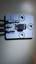
From memory, drain is tab. From left to right G-D-S. They do not populate the center lead.
Do you mean cold solder ball joint? I agree. Solder did not flow.
Do you mean cold solder ball joint? I agree. Solder did not flow.
Hi woofertester, you mean its enough to connect the tab? Is it internally connected to the D lead out? That's good to know. I always had trouble connecting that short center pin.
Woofertester is correct: big tab of LU (drain) connected to D pad. Used a heat gun and SMD solder for the LU - worked perfectly! Solder iron for the wire/pad connectors, with admittedly too much solder build up. But satisfactory for some initial tests.
I also have trouble getting good solder flow on these wire/pad connectors but connectivity seems fine.Woofertester is correct: big tab of LU (drain) connected to D pad. Used a heat gun and SMD solder for the LU - worked perfectly! Solder iron for the wire/pad connectors, with admittedly too much solder build up. But satisfactory for some initial tests.
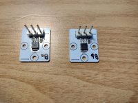
I'd wager he used SMD solder on the upright pins. The problem comes when using 'normal' stick solder to solder wires or other things that you don't have a good jig for & can't easily solder with SMD paste.This is what good looks like. XRK soldered these. You should look at his thread(s) about soldering these.
Okay another great afternoon at the ranch, plowed the driveway with the dozer and came inside and and started playing with the 575 curve tracer. I figured out how to make it work for JFETs and put these LU1014Ds to the test, I'd say they are real. It sure looks like a triode! Darn near a resistor on one of the curves. 😀
I've included a few pics of the setup in case you also have a 575, you can copy the settings. I put a 1K R across the B-E terminals (G-S) to convert the mA/div to Volts/div so 1mA becomes 1 volt on the display. I had the collector volts set to 6, load R was 2R, she got warm pretty fast when I dropped the load to 1R and cranked up the voltage. 😱
Fun fun fun.
Now to try some other devices I have, MOSFETs etc.
Cheers

I have one of those tracers, though it probably needs a refurb after sitting in my basement for ages. I bought if from my last workplace for $50 - such a deal...
- Home
- Amplifiers
- Pass Labs
- LU1014D are these for real?