I am trying to model a simple schematic I found online. Using the .TRAN directive I expect to see an electrolytic cap charge in the 1st 5-10 seconds of the analysis. But I don't get anything like what I expect.
I have used LTspice for years to model musical instrument preamps, so I understand how to use the parts that are familiar to me. And I thought I understood it well enough for this but apparently not.
This circuit comes from this page. Its purpose is to get the mosfet conducting and the load functioning for an initial number of seconds and then turn it off.
Here is my initial LTspice analysis attempt:
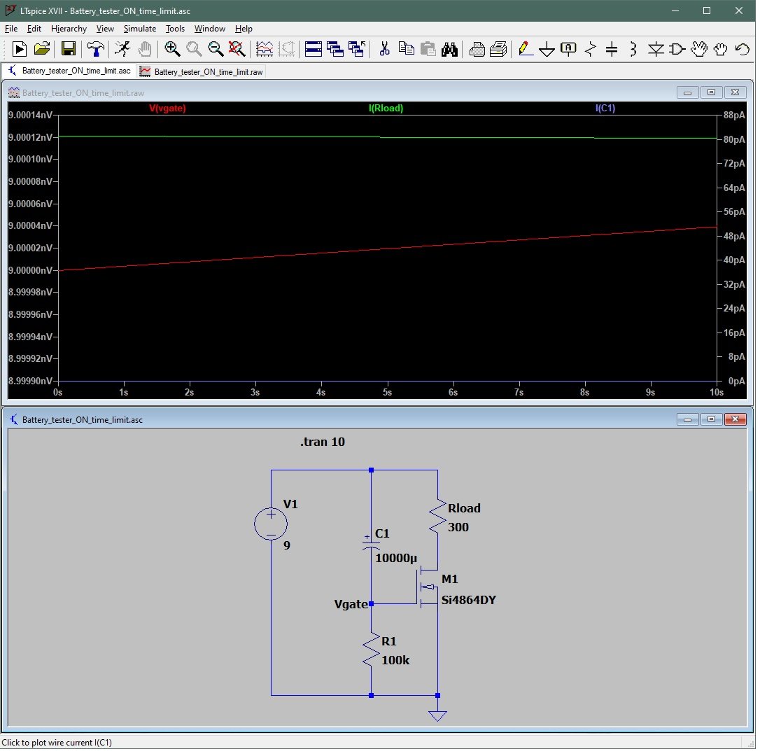
You can see that the voltage at the gate of the mosfet doesn't change, and the mosfet doesn't conduct over the 1st 10 seconds. (It leaks about 82pA). I was expecting the mosfet to conduct while the cap is charging and then to cut off the current through the load as Vgate drops.
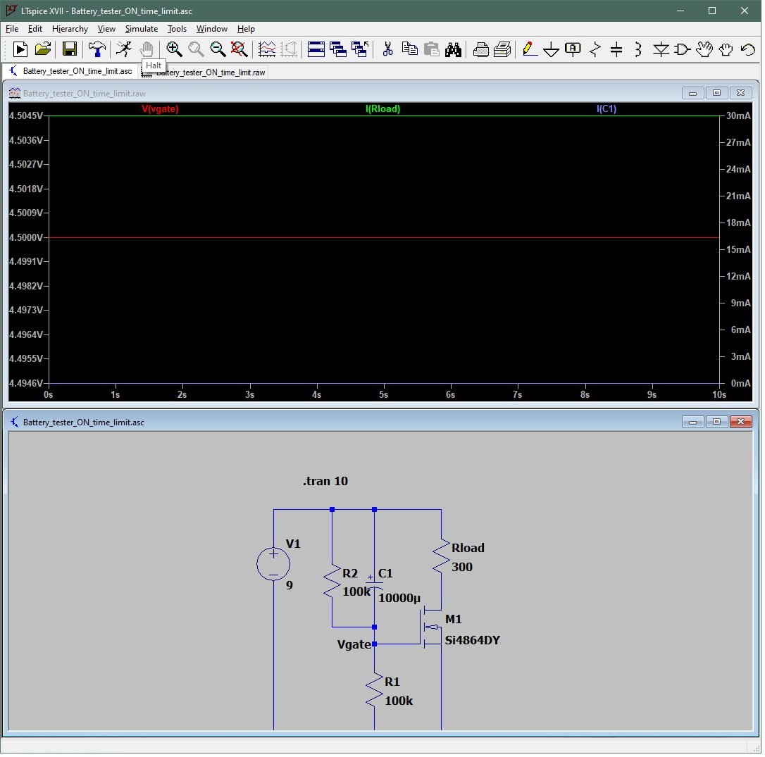
Here is a modified analysis in which we parallel the cap with a resistor so that the mosfet sees 4.5VDC at the gate and now, as expected, the Rload does pass 30mA of current.
Am I doing something wrong? Is there a 'right' way to do this analysis in LTspice? I can breadboard this, but I'd like to know through modeling whether it works as well.
John
I have used LTspice for years to model musical instrument preamps, so I understand how to use the parts that are familiar to me. And I thought I understood it well enough for this but apparently not.
This circuit comes from this page. Its purpose is to get the mosfet conducting and the load functioning for an initial number of seconds and then turn it off.
Here is my initial LTspice analysis attempt:
You can see that the voltage at the gate of the mosfet doesn't change, and the mosfet doesn't conduct over the 1st 10 seconds. (It leaks about 82pA). I was expecting the mosfet to conduct while the cap is charging and then to cut off the current through the load as Vgate drops.
Here is a modified analysis in which we parallel the cap with a resistor so that the mosfet sees 4.5VDC at the gate and now, as expected, the Rload does pass 30mA of current.
Am I doing something wrong? Is there a 'right' way to do this analysis in LTspice? I can breadboard this, but I'd like to know through modeling whether it works as well.
John
Last edited:
The circuit designer expected that the power supply would switch back and forth between 0V and 9V, as the on/off switch is toggled.
I recommend that you change component values so that (R * C) is about ten seconds. Then change LTSPICE component "V1" to be a square wave instead of a constant 9VDC. Set the on time to 40 seconds and the period to 80 seconds. Then run the .tran analysis for 200 seconds.
I recommend that you change component values so that (R * C) is about ten seconds. Then change LTSPICE component "V1" to be a square wave instead of a constant 9VDC. Set the on time to 40 seconds and the period to 80 seconds. Then run the .tran analysis for 200 seconds.
You could do as Mark suggests but another option is to just set it to skip the initial operating point solution.
200 secs is a long time but maybe not long enough to get the gate voltage down to the levels needed by those type of FET's. 300 or more might be needed.
200 secs is a long time but maybe not long enough to get the gate voltage down to the levels needed by those type of FET's. 300 or more might be needed.
Attachments

Yes the normal transient analysis first computes the DC conditions for the circuit (think of all the DC voltage sources starting at negative infinity) - only the time-varying sources start at t = 0. I'd suggest using a pulse voltage source if you are modelling pulse response...
The reason it works like this will become clear if you simulate an amplifier and skip the initial operating point - rather than see the amp's response to the input signal, you see its switch-on transient as well.
The reason it works like this will become clear if you simulate an amplifier and skip the initial operating point - rather than see the amp's response to the input signal, you see its switch-on transient as well.
The edit simulation command also has the option of starting the sim with all voltages at zero - use this and you will see the caps etc charging.
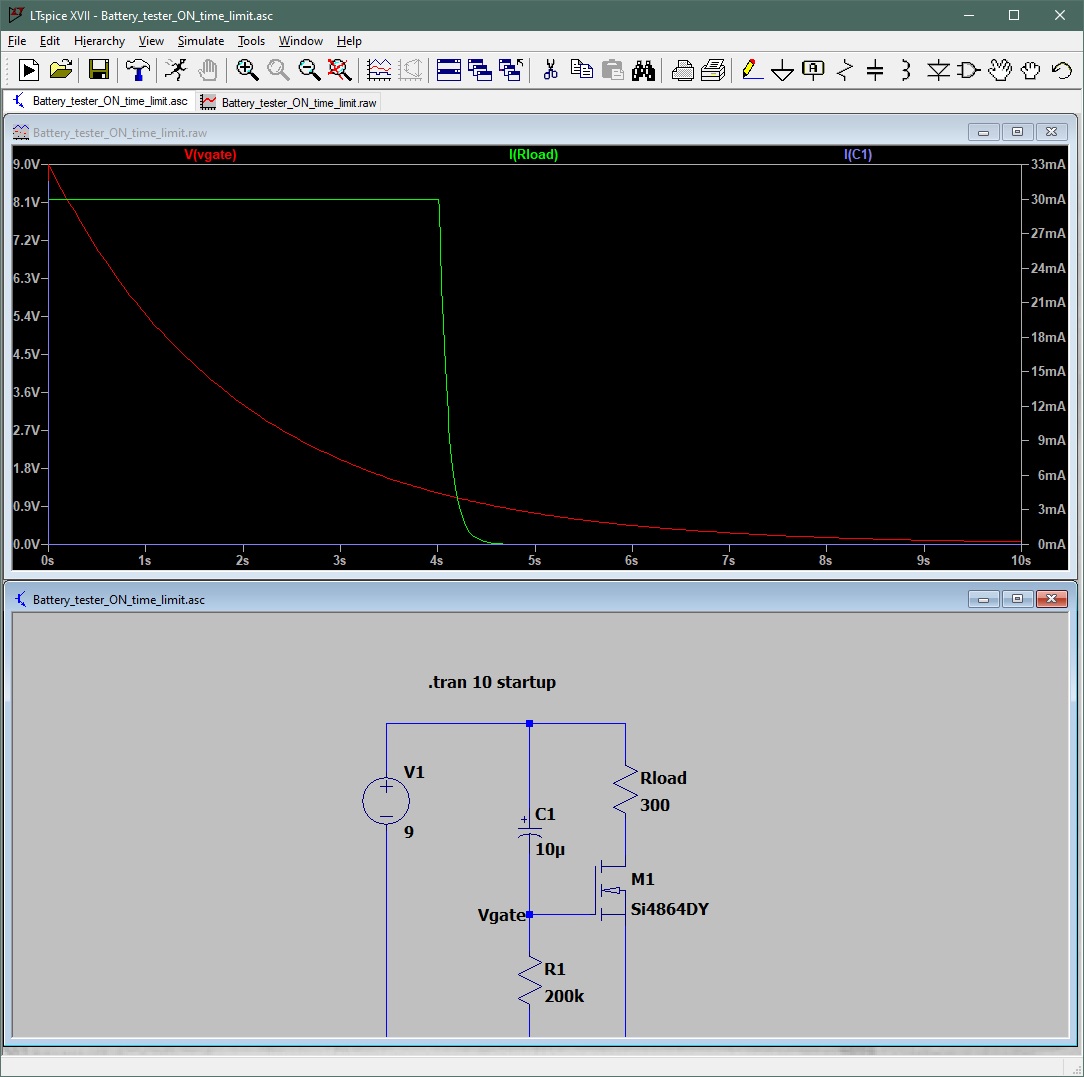
PROBLEM SOLVED:
@Johno hit the nail on the head. I just ticked the "start at zero" option and got this result, with cap and resistor values changed to give me 4 seconds with the mosfet conducting.
DIYaudio is great!
John
@Johno hit the nail on the head. I just ticked the "start at zero" option and got this result, with cap and resistor values changed to give me 4 seconds with the mosfet conducting.
DIYaudio is great!
John
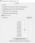
For something like this I would rather use the PWL option in the voltage source.
Just gives you a little more control over everything.
For charging;
- Keep the voltage at 0V at time 0s.
- After 1 sec (can also be smaller), fill in voltage 0V
- Put the time at 1.001 sec for 9V
For discharging basically same thing, but just the other way around
btw, you can ask LTSpice questions in the dedicated LTSpice thread 🙂
Attachments
- Home
- Design & Build
- Software Tools
- LTspice problem? or something else?