Dear keantoken,
with the first jig we would measure the series resistor of the 1u + 100u capacitor ...
Will have a look on the alternate jig...
BR, Toni
with the first jig we would measure the series resistor of the 1u + 100u capacitor ...
Will have a look on the alternate jig...
BR, Toni
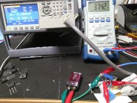
With the second jig first measurement using 2 matched 2SC6145AY
I measure at 10mA (each transistor 5mA) and 8mA (4mA each).
I have added 120R resistors in collector and used a 9V battery for DC biasing to test current sharing - nearly perfect. Measured voltage at common emitter resistor was 4.70 V and in the second case 3.76 V
The last measurements where taken at fixed 12V input, common emitter resistor dc voltage 3.76V (4mA per device).
One file contains the 1u cap measured stand alone.
BR, Toni
Attachments
Last edited:
Unfortunately it seems this method doesn't work, at least not with this equipment. Rb should not increase with current.
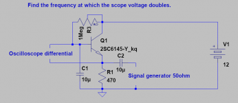
The other option is with a signal generator up to 40MHz or so. The frequency needs to be found where the input voltage doubles for a given emitter current (determined by signal generator impedance). This needs to be done at 2 or more different currents, as it will not correlate well with the meter measurements. I can find the Rb and Irb values that match the results (so square wave input scope shots could also work).
No rush of course, it is up to you.
Attachments
Dear keantoken,
above jig2 values are unusable because of the physical connection of both collector resistors.
BR, Toni
above jig2 values are unusable because of the physical connection of both collector resistors.
BR, Toni
Dear keantoken,
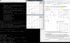
extraction of RE using the flyback method gives different values as your current models have:
RE of 2SC6145AY = 0.0283
RE of 2SA2223AY = 0.0257
See attached picture and ngspice script to visualize and calculate the values.
BR, Toni
extraction of RE using the flyback method gives different values as your current models have:
RE of 2SC6145AY = 0.0283
RE of 2SA2223AY = 0.0257
See attached picture and ngspice script to visualize and calculate the values.
BR, Toni
Attachments
Good work. My suspicion is that those values will result in a much lower Irb value than I got, which will mean RF transconductance of the transistor is better than in the current models. I hope this is correct and it will reflect reality.
Last edited:
What's funny is that the measured Re is the same value as Ron I found from the datasheet. That means Rc is very low. But Dave Zan was burning me for the low Rc in the 2SC3264 model, which is why I raised Rc in these models even though the fit to the data was worse. Go figure.
Can you do the flyback test on RC so we can see what's up? Also a simple reverse Hfe test would be good, as that is also an important parameter for forward operation.
Can you do the flyback test on RC so we can see what's up? Also a simple reverse Hfe test would be good, as that is also an important parameter for forward operation.
Last edited:
Dear keantoken,
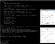
attached the RC values using the same flyback method.
RE of 2SC6145AY = 0.0016
RE of 2SA2223AY = 0.0029
Notes from the author "F.Sischka" of the PDF "Gummel-Poon Modeling":
attached the RC values using the same flyback method.
RE of 2SC6145AY = 0.0016
RE of 2SA2223AY = 0.0029
Notes from the author "F.Sischka" of the PDF "Gummel-Poon Modeling":
as mentioned above, these 'classical' extractions of the ohmic model parameters are used to get a good estimation about the parameter values. The values will be fine-tuned later in the DC setups.
For details on alternate DC modeling methods of the parasitic resistors, see also the publications of /Berkner/ and /MacSweeny/.
If there is a parasitic PNP transistor present, this method will not give accurate RC values.
BR, ToniFor details on alternate DC modeling methods of the parasitic resistors, see also the publications of /Berkner/ and /MacSweeny/.
If there is a parasitic PNP transistor present, this method will not give accurate RC values.
Attachments
And the measured BE resistor using the LCRZ instrument could give us RB (= zero bias base resistance)?
Measurement method "CsRs" series resistor from B to E connection
2SC6145AY = 2.20 ohm
2SA2223AY = 1.98 ohm
Results are relatively constant from 20mV to 100mV and sweep from 25kHz to 100kHz.
Don't know if we can use this values as RB if we calculate for the 6145:
2.20 - 0.0283 = 2.1717
and for the 2223
1.98 - 0.0029 = 1.9771
Some more values from the 2 tested devices:
2SC6145AY:
hFe 83 @ Ic 5mA
Vbe 0.636 @Ib 5mA
Vcesat 0.013 @ Ic 5mA and Ib 1mA
2SA2223AY:
hFe 104 @ Ic 5mA
Vbe 0.628 @Ib 5mA
Vcesat 0.014 @ Ic 5mA and Ib 1mA
BR, TonihFe 83 @ Ic 5mA
Vbe 0.636 @Ib 5mA
Vcesat 0.013 @ Ic 5mA and Ib 1mA
2SA2223AY:
hFe 104 @ Ic 5mA
Vbe 0.628 @Ib 5mA
Vcesat 0.014 @ Ic 5mA and Ib 1mA
Last edited:
BTW: do you know the tool:
It's very accurate to fetch datapoints.
Manually extraction by viewing is difficult when log plots are shown.
BR, Toni
engauge-digitizer
to fetch data points from datasheets?
It's very accurate to fetch datapoints.
Manually extraction by viewing is difficult when log plots are shown.
BR, Toni
I already used it for these and other models.
The current problem is that there is no way to determine Irb. We don't know what Rb is at high currents, and as Dave pointed out the Vbe charts are probably not entirely trustworthy, although they are still the best hint we have.
The current problem is that there is no way to determine Irb. We don't know what Rb is at high currents, and as Dave pointed out the Vbe charts are probably not entirely trustworthy, although they are still the best hint we have.
Dear keantoken,
attached the RC values using the same flyback method.
RE of 2SC6145AY = 0.0016
RE of 2SA2223AY = 0.0029
...
Typo! The correct data is:
RC of 2SC6145AY = 0.0016
RC of 2SA2223AY = 0.0029
BR, Toni
Dear keantoken,I already used it for these and other models.
The current problem is that there is no way to determine Irb. We don't know what Rb is at high currents, and as Dave pointed out the Vbe charts are probably not entirely trustworthy, although they are still the best hint we have.
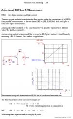
see attached pictures (extract of author "F.Sischka" of the PDF "Gummel-Poon Modeling"; my testdata of 2SC6145).
I have extracted some RBM values during dfferent IB currents. Maybe this helps to interpolate some data using this plot.
If useable let me know, that I can add 2SA2223AY data too.
BR, Toni
P.S.: raw measurement data of 2SC6145AY:
Code:
ib1 values 0.010 0.050 0.0666 0.100 0.200 0.4
vce1 values 0.00143 0.00256 0.00307 0.00404 0.00687 0.01218
vbe1 values 0.660 0.7266 0.7399 0.7593 0.7953 0.8371
Attachments

Last edited:
I entered the data into a spreadsheet. Unfortunately it looks like either the data is wrong or the SGP base resistance model is inadequate.
2SC6145 Rbb modeling - Google Sheets
Here is another idea. Since you have 2 transistors available, you can use one to track the other's Vbe so that it can be removed from the measurement. At multiple currents measure V1 and V2. The difference will be V(Rb) plus some unspecified bandgap voltage depending on Hfe and Vbe mismatch (probably around 120mV for Hfe=100). This voltage will be relatively constant, so can be recorded at low currents and then subtracted at high currents.
Attachments
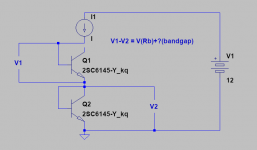
Don't think this method could work. V2 is showing the saturation voltage which decreases very fast at higer currents.
BR, Toni
BR, Toni
Have used the same transistor to get the V2 voltage:
50mA => 0.5744V
66mA => 0.5756V
100mA => 0.6397V
200mA => 0.6619V
400mA => 0.6886V
Does this help to calculate any valid value regarding RB, RBB, RBM, IRB?
BR, Toni
50mA => 0.5744V
66mA => 0.5756V
100mA => 0.6397V
200mA => 0.6619V
400mA => 0.6886V
Does this help to calculate any valid value regarding RB, RBB, RBM, IRB?
BR, Toni
Last edited:
^^^ Here I was wrong - see measurements above: the saturation voltage increases with higher current when the transistor base is directly connected to collector ...😱Don't think this method could work. V2 is showing the saturation voltage which decreases very fast at higer currents.
BR, Toni
We might be getting closer. Can you measure that transistor at 1mA (or possibly lower) with the the collector both shorted to base and open? The difference will give us the bandgap voltage to subtract from the other measurement.
I suggested using 2 transistors so this can all be done quickly in a small time period at the same room temp. The variation in the second transistor shouldn't matter too much as long as we get the low current difference voltage to subtract. It seems sketchy to do the measurements a day apart.
With those values the extrapolated Rb value is unexpectedly low.
2SC6145 Rbb modeling 2 - Google Sheets
- Home
- Design & Build
- Software Tools
- LTspice models for Sanken 2SC6145/A2223