Fellow DIY-ers,
I'm literally stuck between the rails (supply rails that is) trying to model output impedance using LTspice. And yes, I did look at the other threads covering much of the same subject, but I'm still questioning whether I'm not failing in my attempts to do this properly.
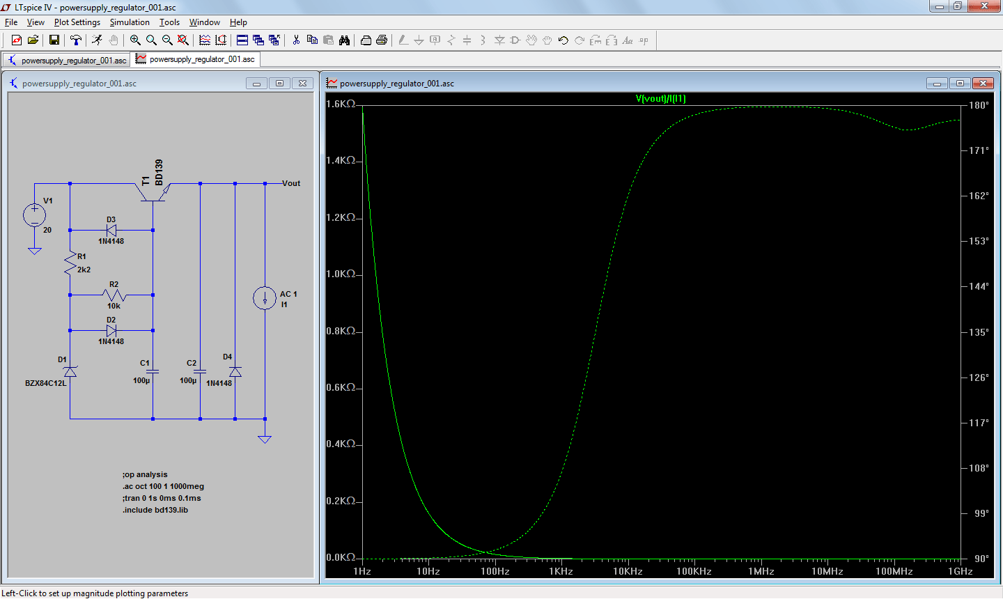
Lets have a look at the below noted circuit, a simple zener voltage regulator for which I want to find the output impedance plotted against frequency.
Here's the steps I've taken to allow LTspice to plot output impedance v.s. frequency:
1) Added a current source to the output.
2) Changed the current source' AC amplitude to 1.
3) Ran the AC analysis and plotted the output voltage V(vout).
4) Clicked (right) on the Y-axis and selected 'Linear'.
5) Clicked (left) V(vout) on top of the plot and added '/I(I1)' behind V(vout).
6) The Y-axis will now plot impedance in Ohms.
7) Considering the value of I1 = 1A and I'm plotting Vout/I1, Y-axis should give Zout in Ohm.
However after looking at the graph plotted I'm left scratching my head though, Zout for such a simple regulator is close to 1 Ohm > 1kHz, that's excellent, but not what I expected, simple zener regulator don't fare that well in my experience?
What am I overlooking here? If any of you fine gentlemen can point out the error in my reasoning, or method of arriving at Zout, I'd appreciate it!
I'm literally stuck between the rails (supply rails that is) trying to model output impedance using LTspice. And yes, I did look at the other threads covering much of the same subject, but I'm still questioning whether I'm not failing in my attempts to do this properly.
Lets have a look at the below noted circuit, a simple zener voltage regulator for which I want to find the output impedance plotted against frequency.
Here's the steps I've taken to allow LTspice to plot output impedance v.s. frequency:
1) Added a current source to the output.
2) Changed the current source' AC amplitude to 1.
3) Ran the AC analysis and plotted the output voltage V(vout).
4) Clicked (right) on the Y-axis and selected 'Linear'.
5) Clicked (left) V(vout) on top of the plot and added '/I(I1)' behind V(vout).
6) The Y-axis will now plot impedance in Ohms.
7) Considering the value of I1 = 1A and I'm plotting Vout/I1, Y-axis should give Zout in Ohm.
However after looking at the graph plotted I'm left scratching my head though, Zout for such a simple regulator is close to 1 Ohm > 1kHz, that's excellent, but not what I expected, simple zener regulator don't fare that well in my experience?
What am I overlooking here? If any of you fine gentlemen can point out the error in my reasoning, or method of arriving at Zout, I'd appreciate it!
Makes sense to me. The 100uf cap alone is 1.6Ω at 1kHz and the Zout vs. frequency curve follows the characteristic of a 1/f response as would be expected without parasitics.
Thanks! You hit the nail on the head, as after tinkering with the capacitor parameters I can get the Zout to change accordingly, i.e. the Zout of this simple zener circuit indeed pretty much relies on the output capacitor for maintaining a low output impedance.
- Status
- Not open for further replies.