For an amplifier.
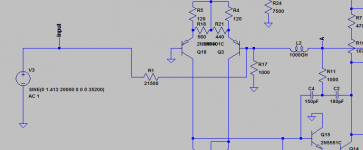
1. Remove/disable input/output filters from schematic.
2. Do an AC analysisis.
3. Probe output from amplifier and see CLG.
Is that correct?
I seem to have a a lot of trouble getting a decent CLG with enough Phase/Gain margin without huge LTP degen resistors, huge compensation caps which leads to low gain crossover frequency(100-200kHz) and it kills the slew rate.
Thought I might be doing something wrong.
Are you sure you mean closed loop gain?
It so easy, see example: you obtain the gain immediately.
But it will tell you little about the loop stability, you would have to look for peaking in the amplitude response and/or rapid phase changes.
The normal tool for analyzing stability is OL analysis.
Post your .asc circuit, it will be easier to show you for real what to do.
Attachments
Last edited:
Open loop gain can be tricky to simulate. In some cases the circuit stops working if you simply remove the feedback. I have had this problem myself and hope to learn something from this thread (will be taking notes).
If you show us the circuit we can take it from there. Make a copy of your .asc file with .txt extension and post that - the forum software will not accept .asc files.
If you show us the circuit we can take it from there. Make a copy of your .asc file with .txt extension and post that - the forum software will not accept .asc files.
Last edited:
You are interested in open loop gain/phase, not in closed loop gain.
Feedback should not be removed, because it will change parameters of the system,
you are trying to analyze (even if you will not have problems with DC operating point).
You need to keep feedback closed, inject signal inside feedback and measure ratio of signals on both ends of injector. For detailed methodology and explanations, check this link:
Loop Gain Simulation - Frank Wiedmann
You are interested in open loop gain/phase, not in closed loop gain.
Dont you mean Loop gain phase and margin? Reading Bob Cordells book it looks like he used Loop gain plot for determining phase and gain margin
Dont you mean Loop gain phase and margin? Reading Bob Cordells book it looks like he used Loop gain plot for determining phase and gain margin
Yes, I was thinking of Loop gain, "Loop gain" is the right term.
You are interested in open loop gain/phase, not in closed loop gain.
Feedback should not be removed, because it will change parameters of the system,
you are trying to analyze (even if you will not have problems with DC operating point).
You need to keep feedback closed, inject signal inside feedback and measure ratio of signals on both ends of injector. For detailed methodology and explanations, check this link:
Loop Gain Simulation - Frank Wiedmann
I was not very clear. System gain/phase, when you are applying signal to the input (the way audio signal will be applied) and measuring system response at the output is not very informative for evaluation of system phase margin. You are getting frequency response of the system and it's phase response, but you can't say how much margin you have.
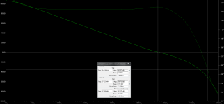
Like this.
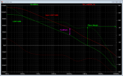
1. Shows Cordells proposed way of plotting the loop gain. 2. Shows LG from my own amplifier.
If I have understood his eaxmples, methods and descriptions of these corretly, this should be correct.
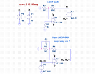
Bob's method (as I can see from your picture) is showing "Open loop gain/phase". It is much more informative, but does not show phase margin. You have to know your feedback gain (or attenuation if you are using passive feedback) and phase. You also making an assumption, that closed feedback will not change parameters of your circuit. This is not true, but could be ignored in some cases. For example, output impedance will be different, but commonly used passive feedback will not provide significant load for the power amplifier.
What you need is "Loop Gain". Attached pictures are showing the way to measure this in simulation, together with one more way to measure "Open Loop Gain".
Attachments

- Status
- Not open for further replies.
- Home
- Design & Build
- Software Tools
- LTSpice, Closed loop gain?