I recently realized how helpful LTSpice can be for running simulations and decided it might be helpful for others as well. I'm a novice user of LTSpice so take this all with a grain of salt.
I've been working with MJ King's "Simple Sizing of the Components in a Baffle Step Correction Circuit" and specifically Hong Nguyen's spreadsheet (based on King's work) to design a BSC circuit for a pair of speakers I built a few years ago. I have used various forms of equalization in the past and wasn't very happy with any of them.
Anyway, I wanted to really learn what this BSC circuit was doing - what each component actually does. I am a visual learner so being able to run simulations is helpful to me. Maybe it is to you, too.
So basically all I did was install LTSpice (it runs great in Linux under WINE, by the way) and then I spent some time getting used to the interface, how to place various components, rotate them, connect wires to the components, add and edit a voltage source, use hotkeys, etc. I won't include these basic instructions because a quick google will get anyone started.
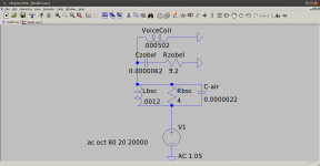
I used Mr. Nguyen's spreadsheet to calculate (BSC + Zobel) component values and then built the simulation in LTSpice based on the diagram on the spreadsheet. To simulate the speaker, I used an inductor with a value equal to the voice coil inductance and also entered the series resistance of the voice coil. The AC voltage source wasn't easy to figure out. Basically, you have to click the "Component" object button and then find "Voltage", then place the object on the screen. It defaults to DC so you need to right-click it and then find a section named "Small signal AC analysis" and enter an AC voltage value in the "AC Amplitude" box. I started with 1.6 volts and then adjusted it later.
So once you get the voltage source, the BSC and Zobel components, wiring, speaker wired up and configured with the right values you can move on to the simulation. By the way, there are online calculators to convert uF to Farads, mH to Henry, etc. Make sure you get the correct values entered into each component.
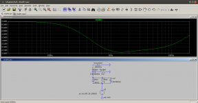
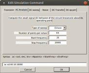
One of the screenshots attached shows the complete circuit setup, with an example of how to create an AC voltage sweep simulation. To set that up you need to go to the "Simulate" menu and then click "Edit simulation Cmd". My screenshot shows how to set up a 20Hz to 20000Hz AC "octave" sweep. Once that is set up, you can simply click the "Run" button on the button bar and new graph window will open to display the results - but there is one thing left to do. Take your "probe" (mouse pointer) and click on the "wire" just before the speaker voice coil. The graph will display the 20Hz to 20000Hz sweep after it has gone through the BSC filter (as you can see in the screenshot).
One thing to note; there is an extra component in my BSC filter here - the 2.2uF cap. I added this to pull the ~8kHz-20kHz range back up a bit, since my speakers roll off considerably after 10kHz. Removal of this component results in a typical BSC filter, where the response stays flat out to 20kHz.
Depending what AC amplitude (voltage) you specify, the "0 dB" point on your graph might not align well at all. I simply went and adjusted that value multiple times till the simulation accurately showed 0 db at the top of the bass curve (at 20Hz). This was for personal preference only.
I am happy to say I have built two of these BSC/Zobel + Air circuits and I they sound excellent! Far better than a miniDSP or run-of-the-mill solid state EQ, IMO.
EDIT: added sweep simulation setup screenshot
I've been working with MJ King's "Simple Sizing of the Components in a Baffle Step Correction Circuit" and specifically Hong Nguyen's spreadsheet (based on King's work) to design a BSC circuit for a pair of speakers I built a few years ago. I have used various forms of equalization in the past and wasn't very happy with any of them.
Anyway, I wanted to really learn what this BSC circuit was doing - what each component actually does. I am a visual learner so being able to run simulations is helpful to me. Maybe it is to you, too.
So basically all I did was install LTSpice (it runs great in Linux under WINE, by the way) and then I spent some time getting used to the interface, how to place various components, rotate them, connect wires to the components, add and edit a voltage source, use hotkeys, etc. I won't include these basic instructions because a quick google will get anyone started.
I used Mr. Nguyen's spreadsheet to calculate (BSC + Zobel) component values and then built the simulation in LTSpice based on the diagram on the spreadsheet. To simulate the speaker, I used an inductor with a value equal to the voice coil inductance and also entered the series resistance of the voice coil. The AC voltage source wasn't easy to figure out. Basically, you have to click the "Component" object button and then find "Voltage", then place the object on the screen. It defaults to DC so you need to right-click it and then find a section named "Small signal AC analysis" and enter an AC voltage value in the "AC Amplitude" box. I started with 1.6 volts and then adjusted it later.
So once you get the voltage source, the BSC and Zobel components, wiring, speaker wired up and configured with the right values you can move on to the simulation. By the way, there are online calculators to convert uF to Farads, mH to Henry, etc. Make sure you get the correct values entered into each component.
One of the screenshots attached shows the complete circuit setup, with an example of how to create an AC voltage sweep simulation. To set that up you need to go to the "Simulate" menu and then click "Edit simulation Cmd". My screenshot shows how to set up a 20Hz to 20000Hz AC "octave" sweep. Once that is set up, you can simply click the "Run" button on the button bar and new graph window will open to display the results - but there is one thing left to do. Take your "probe" (mouse pointer) and click on the "wire" just before the speaker voice coil. The graph will display the 20Hz to 20000Hz sweep after it has gone through the BSC filter (as you can see in the screenshot).
One thing to note; there is an extra component in my BSC filter here - the 2.2uF cap. I added this to pull the ~8kHz-20kHz range back up a bit, since my speakers roll off considerably after 10kHz. Removal of this component results in a typical BSC filter, where the response stays flat out to 20kHz.
Depending what AC amplitude (voltage) you specify, the "0 dB" point on your graph might not align well at all. I simply went and adjusted that value multiple times till the simulation accurately showed 0 db at the top of the bass curve (at 20Hz). This was for personal preference only.
I am happy to say I have built two of these BSC/Zobel + Air circuits and I they sound excellent! Far better than a miniDSP or run-of-the-mill solid state EQ, IMO.
EDIT: added sweep simulation setup screenshot
Attachments
Last edited:
Why not use any of the speaker simulation applications out there? They do the same and are probably easier to use.. as for miniDSP: you can recreate the exact filter response as a series of biquads. The result will be equivalent.
Of course as an exercise to get to know LTSpice this is quite a nice starting project.
Of course as an exercise to get to know LTSpice this is quite a nice starting project.
The TS parameters of a driver have an equivalent circuit of RLC - you can even set up your driver represented as a bunch of components. Then see how the BSC interacts with the driver and amp.
In my speaker simulation software, Akabak, I often add a BSC directly and use it to put a shelf attenuation above about 800Hz where most baffle steps are located for average cabinet.
In which case (for 8ohm speaker) use a 1mH coil and add 1R, 2.2R, 3.3R, 4.7R, 6.8R, or max 10R in parallel until it sounds good and balanced. Adding a 0.47uF cap in parallel will bring back some highs as you mention. But really no need to simulate it other than to understand what it does. In practice, 1mH and hand full of resistors is all you need.
I often run my BSC externally so I can change R’s until it sounds good. Then button it up inside the cabinet.
Why not use any of the speaker simulation applications out there? They do the same and are probably easier to use.. as for miniDSP: you can recreate the exact filter response as a series of biquads. The result will be equivalent.
Of course as an exercise to get to know LTSpice this is quite a nice starting project.
I had no idea there are speaker simulation applications out there. 🙂
The miniDSP is barely acceptable to me as a line-level device, and in this regard is only useful for one source. It is totally unacceptable in a situation where it comes after a pre-amp, which is why I only used it for a few months before decommissioning it.
With this BSC filter, I have zero need for EQ (neither analog nor digital) and I can clearly hear that none of those devices are getting in the way now. We all prefer different things, however. 🙂
The miniDSP is barely acceptable to me as a line-level device, and in this regard is only useful for one source. It is totally unacceptable in a situation where it comes after a pre-amp, which is why I only used it for a few months before decommissioning it.
Those are valid reasons to have. My point was more regarding the filters equivalence.
With this BSC filter, I have zero need for EQ (neither analog nor digital) and I can clearly hear that none of those devices are getting in the way now. We all prefer different things, however. 🙂
Surely, if a simple passive filter will do for a full range system, there is no reason to not use it.
Last edited:
The TS parameters of a driver have an equivalent circuit of RLC - you can even set up your driver represented as a bunch of components. Then see how the BSC interacts with the driver and amp.
In my speaker simulation software, Akabak, I often add a BSC directly and use it to put a shelf attenuation above about 800Hz where most baffle steps are located for average cabinet.
In which case (for 8ohm speaker) use a 1mH coil and add 1R, 2.2R, 3.3R, 4.7R, 6.8R, or max 10R in parallel until it sounds good and balanced. Adding a 0.47uF cap in parallel will bring back some highs as you mention. But really no need to simulate it other than to understand what it does. In practice, 1mH and hand full of resistors is all you need.
I often run my BSC externally so I can change R’s until it sounds good. Then button it up inside the cabinet.
I forgot to thank you for the help adding the "air" cap. I couldn't wrap my head around the math that you posted (in the other thread), but playing with it in LTSpice really solidified (at least) the concept of what is going on.
The fact that I can change component values and then re-run the simulation is both fun and educational. It has become obvious that it is not possible to simply change one component value too much without throwing off the "synergy" of the balanced filter.
I did simulate and then test a "stronger" filter before this one but it was readily obvious that I had overdone it. My wife even said "it's just not 'clear' any more". I guessed that there might be a few iterations of this filter so they are running outside the boxes right now. I plan to listen this way for a couple of weeks with lots of different source material until I am 100% certain - then find somewhere to hide them away. Probably mounted on the back of the speakers, connected with banana plugs so they can be easily bypassed if desired.
Those are valid reasons to have. My point was more regarding the filters equivalence.
I suppose my response revealed that I didn't understand your point about biquads. I don't know nearly enough as I should about the theories surrounding any of this stuff.
Surely, if a simple passive filter will do for a full range system, there is no reason to not use it.
Indeed. Especially if (like me) your goal is to get your digital sources back to analog as cleanly as possible and then keep it the analog realm until it hits your ears, preferably with as little "mud" and as much "life" as possible.
Overall, this thread is really about my late-onset interest/learning about LTSpice and how the various components work to filter different frequencies. I was delighted that I figured it out and that it played out in reality so I decided to share (for those other luddites or newbs out there).
Last edited:
One other thing to note: I decided to physically measure the series resistance of my inductors and enter the real value (0.4 ohm) into the simulation. I was surprised how much this changed the simulation. I have read somewhere that "an ohm or two" coil SR won't be a big deal in a BSC. I now disagree quite strongly with that idea.
I assume this value is not included in the math on Mr. Nguyen's spreadsheet. It is just a guideline to begin experimenting, of course - but the SR of the coil definitely makes a very significant difference. Based on what I have seen, I will always choose coils with the lowest SR that I can afford (I made the right choice quite by accident this time!). Attenuating the bass more than necessary (by using higher SR coils) means that you need to also increase the parallel resistor value to achieve an adequate relative reduction of dB in the upper frequencies. This all spells "lower efficiency". For people who are running only a few watts, this could become a problem.
And finally, my ears like the sound of wirewound resistors better than metal oxide. At resistance values this low, the miniscule inductance of the wirewounds is negligible.
Last edited:
- Home
- Loudspeakers
- Full Range
- LTSpice BSC Simulation Success