The only thing you can do with cshunt is to simulate the presence of a ground plane. It is somewhat unrealistic that each node would have the same cshunt to ground since the nodes have different routing length, hence different capacitance.[…] in the end the Cshunt directive is still the true king. […]
Most PCB designs I have seen on this forum do not feature a ground plane however.
A more useful approach would be to add cshunt to specific nodes only in order to identify those that are impacted by cshunt the most and then to avoid cshunt during PCB design.
I see that you have 2pF / 5pF caps in your schematic that seem to have a purpose. Clearly, adding cshunt here will likely mess up your circuits operation. Better avoid such small capacitors because PCB design may add significant capacitance and then the schematic looks different and the circuit works differently.
You're absolutely right!The only thing you can do with cshunt is to simulate the presence of a ground plane. It is somewhat unrealistic that each node would have the same cshunt to ground since the nodes have different routing length, hence different capacitance.
Most PCB designs I have seen on this forum do not feature a ground plane however.
A more useful approach would be to add cshunt to specific nodes only in order to identify those that are impacted by cshunt the most and then to avoid cshunt during PCB design.
I see that you have 2pF / 5pF caps in your schematic that seem to have a purpose. Clearly, adding cshunt here will likely mess up your circuits operation. Better avoid such small capacitors because PCB design may add significant capacitance and then the schematic looks different and the circuit works differently.
I corrected the 2pF to 5pf just to get a good bode and step response in the simulations i posted here.The true values for that capacitance are much higher in real circuits, but that's also tied to the op amp used .LT 1056 model is a highly convenient one for simulations, but also a very fast op amp so less capacitance is needed for compensations.And I also have a good gain and high values for the feedback resistor network so it's kinda natural.I used 2pF in my headphones amp using almost identical topology with opa2132 and germanium transistors...and it worked very well.When I swaped for lm6172 there was an extention in the highs that looked more like quicly damped oscillations( no measurement done) but I suspect the slightly higher level of highs being actually damped oscillations.
When i switch the simulation to nonivering topology i need about 100pF to get the same stability.My final op amp of choice would be opa2132 or opa2228 with a lean towards jfet input op amps immunity to emi.
Last edited:
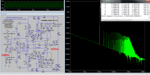
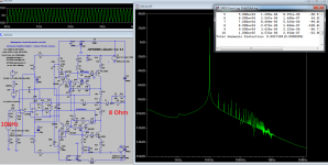
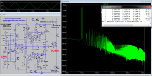
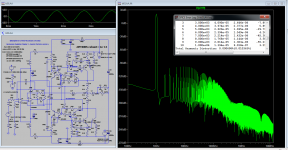
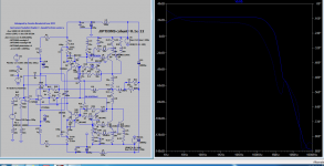
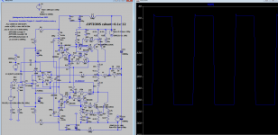
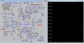
Here's a slightly better and more interesting version I simply called V5.I bought some 150V 10 amps schotky diodes for the previous version which was truthful to the Kenwood kl01A output stage with the intention of building a full class B amp but I also thought of trying some transistors instead of those diodes which odly enough got me a slightly better distortions profile.For the class b version i can definitely use germanium transistors for q4, q5 and silicon trz for q1, q2 or just schotky diodes instead q4q5.Basically , without those diodes you're within normal Szyklay territory where distortions are at least an order of magnitude higher.
I thought of making 4 amplifiers ,2 for base section using silicon trz working at max +-21V and 2 for mids_highs using germanium trz and working at just +-12V but the paralleled output section might be used with germanium trz as well.
I think this long exercice(almost 6 months now...) around this architecture brought me to the best of all possible class AB amps for low power as +-21v would be kind of the max supply voltage you can safely use with some good op-amps although a +-15V supply would allow for enough power into 8 ohms if you have sensitive speakers. In 2 ohms I can get about 110 watts of very clean power . Getting this architecture into pure class B with very low distortions is fairly easy too but we already have a lot of talks on the subject.
Attachments
-
 V5.png38.8 KB · Views: 72
 -
 V5A.png40.6 KB · Views: 66
 -
 V5B.png40.1 KB · Views: 62
 -
 V5C.png41 KB · Views: 72
 -
 V5D.png41.9 KB · Views: 67
 -
 V5E.png44.4 KB · Views: 64
 -
 V5bode.png36.1 KB · Views: 65
 -
 V5stepr.png31.4 KB · Views: 68
 -
 V5humlevel.png35.5 KB · Views: 64
 -
 V5noise.png36.2 KB · Views: 69
 -
kl01AAA.asc14.6 KB · Views: 63
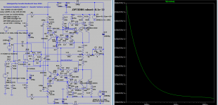
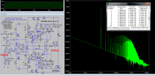
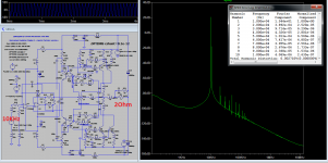
Even though I miss some interaction with people, I'll just post the next best sym.I tried to meet the Kulish error corrector conditions, but I found difficult to get it work inside the kenwood l01a output stage without raising the idle current and this buffer is already so optimized by the bootstrap itself that I can't get much better results even with 4 times higher idle current throwing me in deep class A region.At least the first version shows the same stability pattern and half the idle current of the previous versions which makes me hopeful even more. The idle current graph actually shows some hum ripple superimposed that I allowed into the system.
Attachments
Last edited: