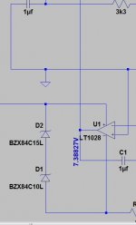
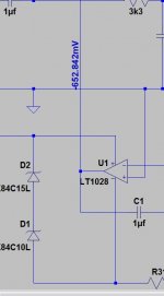
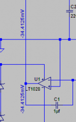
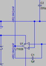
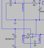
The two pictures show part of the same circuit. When I run the ".op" command to simulate DC conditions I find the opamp output line can show different voltages depending where on the line is clicked. Hovering the cursor shows the correct voltage (around 7 volts). If I then click below the opamp to tag that line with the voltage it is correct. If I do the same again but tag the line above the opamp then an incorrect voltage is placed.
Is this a glitch or am I doing something fundamentally wrong ?
Is this a glitch or am I doing something fundamentally wrong ?
Attachments
Actually, this is not supposed to happen!
Spice does *not* know about different 'places' along a wire - all circuit points connected by wires/lines belong to the same so called 'node', they are regarded as one point without dimensions. All calculations are made for these nodes (listed in the netlist file), and everything belonging to a node shares the same properties. Maybe it is a problem with the graphical user interface.
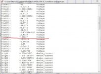
If you're inclined, check the raw data output for the values assigned to that node.
Greetings,
Andreas
Spice does *not* know about different 'places' along a wire - all circuit points connected by wires/lines belong to the same so called 'node', they are regarded as one point without dimensions. All calculations are made for these nodes (listed in the netlist file), and everything belonging to a node shares the same properties. Maybe it is a problem with the graphical user interface.
If you're inclined, check the raw data output for the values assigned to that node.
Greetings,
Andreas
It seems that in the right pic, you're reading a different wire. Look at the small tag handle below the '6'.
jan
jan
Thats no tag handle, but the 'minus' sign in that crappy font! 🙂
EDIT: And the other wire is connected to the 'ground' node, which is always zero potential in Spice - so the reading is definitely *not* from the horizontally crossing wire...
EDIT: And the other wire is connected to the 'ground' node, which is always zero potential in Spice - so the reading is definitely *not* from the horizontally crossing wire...
I've had this sort of thing happen when moving components, they appear to drop in place but don't always connect. Maybe the opamp output isn't really connected? I end up just deleting and remaking the wire connections.
..err that's not right, but there must be a break in that wire that just isn't visible --> delete and redo
..err that's not right, but there must be a break in that wire that just isn't visible --> delete and redo
Last edited:
I haven't noticed that problem with LTSpice, but it seems to be (too) common in Multisim.I've had this sort of thing happen when moving components, they appear to drop in place but don't always connect. . . .
Whenever a program - not just circuit simulators, but ANY program - has a "mouse over to see <some kind of information> " feature, it's not always easy to determine WHICH object is being referenced. Sometimes it seems to be the object at the point of the cursor, other times it's an object under the cursor, and occasionally it seems to be some random object in the general vicinity of the cursor.
With LTSpice, as you move the cursor around you can get the message in the lower ribbon bar, e.g., "DC operating point V(pre_out) = 12.34 mV". At least that tells you which node LTSpice thinks you're interested in, though the default node assignments ( "V(n0008)", for example) are pretty cryptic. That encourages me to select the handful of nets that I'm especially interested in and give them explicit names.
Dale
you can grab, drag/move lines/parts slightly to see where/if the connections are made with the mouse button held, then drop back in place or use undo if your movement messed up the connection
you can also highlight a net
you can also highlight a net
Last edited:
Mooly,
If you really think there's a problem with LTSpice, report a bug (click on the Help, About ltSpice). If you have a real point, and aren't just blowing smoke, then Mike Englehardt will be very happy to respond - I've written him several times and gotten very cordial responses.
Bill
If you really think there's a problem with LTSpice, report a bug (click on the Help, About ltSpice). If you have a real point, and aren't just blowing smoke, then Mike Englehardt will be very happy to respond - I've written him several times and gotten very cordial responses.
Bill
..........If you're inclined, check the raw data output for the values assigned to that node.
Greetings,
Andreas
Thanks... that seems to show a problem. The node is V (no32). When I tag the node above the opamp and then hover over it the node has changed to V (no23)
The only difference bewtween "Test1" and "Test2" is the tagging of the line. The curcsor was hovering over the line each time the screen grab was taken.
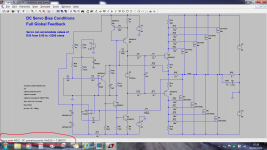
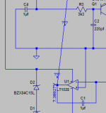
Can we see the whole circuit?
Here's the exact file that's causing the problem.
Attachments

Using the node highlight function, try to find out which parts of the circuit belong to the two nodes N023 and N032 - maybe that shows why LTSpice is confusing them...
EDIT: If you don't want to rely on the graphic interface, check the netlist file created by the schematic editor for the entries of N023 and N032 and find out where the two nodes are in the circuit.
EDIT: If you don't want to rely on the graphic interface, check the netlist file created by the schematic editor for the entries of N023 and N032 and find out where the two nodes are in the circuit.
Last edited:
"Node highlight" ?
I've never used that and as a Spice newbie I'll have to look at how to do that.
I've never used that and as a Spice newbie I'll have to look at how to do that.
If a 'Newbie' anyway, better to learn the 'good' way and have a look at the netlist file! 😉
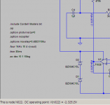
EDIT: Just had a look at the LTSpice schematic editor and it does not seem to be able to higlight nodes. If you look at the netlist file (open the file using a text editor or let LTSpice show the netlist via the menu entry), you will find a line for each component:
[component name] [connection1] ... [connection n] [component properties]
Now look for N023 and N032 and check in the schematic to which components these two nodes are connected.
Last edited:
Node 23 seems to be the emitter of Q7. When I tag the opamp line this node changes to from node 23 to node 24 !
😀
If a 'Newbie' anyway, better to learn the 'good' way and have a look at the netlist file! 😉
😀
Node 23 seems to be the emitter of Q7. When I tag the opamp line this node changes to from node 23 to node 24 !
This hints at a problem with the schematic editor / user interface - the netlist is determined by the schematic and does not change unless you change the schematic, i.e. not by clicking/tagging anything. Looks as if the tagging function randomly selects wrong nodes when clicking anything.
Looking into the netlist will clear things up I hope.
Definitely looks like a bug to me!!! It shows 7V when I hover over any point on that line. If I click on the lower part it puts 7V If I then click on the upper part, it puts 34mV (and the lower one changes from 7V to 34mV.
I deleted the two tags and did it again. this time it started with 7V and then when I clicked above it got -652mV... (for both places) very odd!!
and yes node 023 is the emitter of Q7!!
I tried dragging R29 to show that there were no breaks in the line, and now I cannot get a tag anywhere on that non-straight line it just gives ???! I suspect that there is a bug in the interface that is not properly picking up the co-ordinates of the mouse when you click to add the tag. It is certainly reproducable with the model you have attached though, so should make things easy to report if you want to do a bug report!
edit: I did it one more time and this time it was -2.32V and node 022 which I think should be the -ve input of the opamp which it is now showing at 7V and node N032!! It seems this time it has swapped the negative input and the output!
Tony.
Attachments
Last edited:
The answer to that is "it depends" 😉 when there are no tags it is where it is supposed to be. But when The tags are in place (at least the last one I did) it changed to N024!!!!
Tony.
Tony.
- Status
- Not open for further replies.
- Home
- Design & Build
- Software Tools
- LTSpice anomaly. Same wire, different voltages.