I was reading the Morgan Jones book and am having trouble understanding one aspect of a circuit. On page 136 he shows a LTP configuration with CCS tail and plate loads.
In a configuration such as this, what fixes the plate voltage? Just looking at the circuit and plate curves it seems that since there is no fixed resistance value for a plate resistor or cathode resistor, there would be no fixed operating point.
Please help me understand this if I am missing something here.
Let me better explain my confusion. The tail CCS can set the bias voltage on the grid to whatever it wants to. However, the plate load CCSs can adjust their resistance to whatever it needs to be at any given bias. Don't know if that makes any sense. I'll work on posting an example picture so that those who can't picture this circuit can look at something.
Morgan gave the answer: "Fine adjustment of the tail current sets anode voltages". In other words, it's determined by trial.
In this application, the single transistor plate loads have lower impedance than the cascaded cathode load. They are intended to act as relatively high impedance plate loads when the B+ is not high enough for a high value resistor. You don't want a perfect CCS in both plate and cathode - that would be an immovable object meeting an irresistible force. So the cathode load dominates and the adjustment is made there.
Sheldon
I also have difficulty with this concept. CCS tail and plate loading is a good idea, to get the best balance in the LTP and the most linear performance from the triodes. In fact, it's hard to imagine anyone ever using resistors by choice, even if they have plenty of B+ available.
But how do you know what the plate voltage is going to be? It can be important if you're using DC coupling to the next stage.
Well, one way out of the dilemma is to set each plate CCS to slightly less that 50% of the current in the tail CCS and connect a high value resistor in parallel with the plate CCS. The difference in current is forced to go through this resistor, so its value multiplied by the current difference determines the voltage drop across it. If the difference in current is small (say, 50uA), then the parallel resistor value can be high (much higher than an ordinary plate load resistor would be without a CCS), so you still get the benefit of having a really high value plate load.
It would all have to be adjusted and set by experimentation to get equal plate voltages, because of the tolerance of the components involved. I can't see it being used in commercial amps - every case would be different!
Ray:
I've always had the same difficulty with this circuit concept, and I agree with the resistor idea. I call it a ballast resistor, not sure if that's appropriate or not. You could also connect it from plate to common, I would think, and ohm's law determines plate voltage by imbalanced current.
I've always had the same difficulty with this circuit concept, and I agree with the resistor idea. I call it a ballast resistor, not sure if that's appropriate or not. You could also connect it from plate to common, I would think, and ohm's law determines plate voltage by imbalanced current.
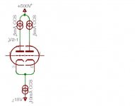
SpreadSpectrum said:Here's a picture for an example.
I'm afraid of a moderator to comment such ideas, sorry...
But you may use my CCS with servo to make this thingy usable:
Upper PNP transistor may be replaced by a FET to get as high as possible dynamic resistance (degraded because base current is needed!)
Thanks, Wavebourn. It makes sense, if we're going to use controlled current imbalance between tail CCS and plate CCSs, with 'ballast resistors' (I like that term) to take up the current 'slack', then the plate CCSs might just as well use good PNP transistor cascodes, as opposed to an inferior single transistor, since we're no longer relying on the dominance of the tail CCS.
The idea is not just a transistor cascode; the upper transistor adjust the current such a way that the voltage on the plate is determined by ratio between resistors R2 and R3. It acts as a combined AC current source and a DC voltage regulator. With such a load you may vary the cathode current as you want, but voltages on anodes will be always the same and stable.
As I understand the circuit, it is a current source that prefers to set its resistance to a certain value under DC conditions, thus assuring that the plate voltage has a quiescent value. I will have to build one of these and try it out.
Looking back at the example in the Jones book, total current in the plate CCSs is .775mA and tail current would be .62mA, so I am guessing that somehow this CCS imbalance produces some stable plate voltage. However, I don't understand the mechanism for this and how to predict what the plate voltage would be. I guess that's what he means by, 'Fine adjustment of the tail current sets anode voltages.' I hadn't run the numbers and notice that there was an imbalance here before. I haven't built one of these yet. Maybe I will will have to soon...
I am thinking that building one with equal plate and cathode CCSs would result in strange behavior. Again, I will have to build one and see.
If I had to guess, the 10k resistor in the cathode CCS of Fig 2.49 should be shown as a trimmer.
SpreadSpectrum said:As I understand the circuit, it is a current source that prefers to set its resistance to a certain value under DC conditions, thus assuring that the plate voltage has a quiescent value. I will have to build one of these and try it out.
If you mean my CCS with servo, it's resistance is always the same, but current varies depending on a voltage it senses. Strictly speaking, it is not a CCS, but a high dynamic resistance load with a constant voltage drop.
I am thinking that building one with equal plate and cathode CCSs would result in strange behavior. Again, I will have to build one and see.
It will be very unstable.
SpreadSpectrum said:
Looking back at the example in the Jones book, total current in the plate CCSs is .775mA and tail current would be .62mA, so I am guessing that somehow this CCS imbalance produces some stable plate voltage.
Hi Spectrum ,
I think that , it is not the exact way to interpret the " thing ".
Do not forget that the CCS plate loads , are using PNP transistors
so , the difference between currents ( .775 - .620 mA ) , will flow
INTO the base circuit , and then to the ground through the 27 K
x 2 W resistor . Do you agree ?
Regards ,
Carlos
I am thinking that building one with equal plate and cathode CCSs would result in strange behavior. Again, I will have to build one and see.
It will be very unstable.
I once got the idea that if one CCS was good two would be better, so I built a standard common cathode amplifier with a CCS in the cathode and another in the plate. I was thinking split (CCS) load phase splitter. What I found out is that you can not build two CCS circuits that conduct exactly the came current over all conditions including temperature. This results in bi-stable operation. The plate or cathode voltages will randomly snap from one extreme to the other and linear operation is unlikely.
I have not tried to build a triple CCS LTP but I can imagine that it would be hard to set up and would not be distortion free over a wide temperature range.
The use of a triple CCS has also been discussed in this thread.
http://www.diyaudio.com/forums/showthread.php?s=&threadid=111099
Erik
http://www.diyaudio.com/forums/showthread.php?s=&threadid=111099
Erik
The Jones circuit has two constant current sources both trying to define the current in the same wire. Obviously, if they were perfect constant current sources that would be impossible. There are various ways in which practical circuits can be made to work, and they usually rely on the fact that a practical constant current sink has a finite output resistance, so change in current through it results in a predictable voltage change across that output resistance:
(1). Identical constant current sources. A circuit using DN2540N5 JFET constant current sources connected in series has proven to be stable over several years. The caveat is that the devices were matched, they're nearby on the same heatsink, and they only ever see a sine wave signal. This is the least stable configuration, hence the requirement for matching the devices so that they drift their current in the same way and matching their operating conditions so that they drift current by the same amount, resulting in no voltage change. As tubelab proved by experiment, you haven't a hope of matching PNP to NPN.
(2). Different constant current sources: If one constant current source is far superior to the other, it can enforce its behaviour upon the other. In this instance, one constant current sink might have an output resistance of 1M, but the other 100M. Adjusting the current setting of the 100M CCS will change the voltage across the 1M CCS. The slope of the 1M CCS won't change appreciably with temperature, so the stability of the final circuit is down to the behaviour of the 100M CCS. The 100M CCS might be enforcing 1mA DC through the 1M CCS, so (by Ohm's law) a 1uA change in current would cause a 1V change in voltage across the 1M CCS. 1uA change would be 0.1% of 1mA, and is achievable without any special care. The LED and ordinary resistor in the circuit being discussed should be stable to <1% drift in current, resulting in <10V drift in anode voltage, which is perfectly acceptable. The trick in this implementation is that one CCS must be much better than the other, hence the cascode CCS in the cathode and the crude CCSs in the anode circuits.
(3). Wrap a DC servo round the circuit. Wavebourn's circuit has voltage feedback from the output of the CCS to its reference input and holds the output voltage constant. At first sight, that stops the circuit being an active load, but the feedback is short-circuited at AC by C1, allowing it to work as a CCS at AC. The R3C1 time constant needs to be large to maintain CCS operation over the audio band. At AC, C1 is a short circuit, so R3 is like ray_moth's ballast resistor in parallel with the CCS, so it has to be large. If we assume a value of 10M for R3, then 10n for C1 would be adequate down to almost 1Hz.
EC8010:
Thanks for the explanation. You got right to the heart of the question.
I guess all that remains now is to build these and see how they perform. The solution of having the differing CCSs appeals to me due to the simplicity factor, but I will have to build both that and the DC servo and measure performance before I make a final decision as to which I will use. I will report back when I do, but it won't be anytime too soon.
Thanks for all the help everyone.
- Status
- Not open for further replies.
- Home
- Amplifiers
- Tubes / Valves
- LTP w/CCS tail and plate loads