I chased this down maybe 20 years ago. Mr. Miller and his unwanted capacitance steals your HF response. As others have stated the resistor at the grid pin must be lower. I use 1 to 4.7K.
More plate current is the way to better HF response.
So 5687 or 7119 with appropriate plate & cathode tail resistors is a start.
A bit like performance cars, 'there is no substitute for cubic inches'.
That should say something about how olde I am.
So 5687 or 7119 with appropriate plate & cathode tail resistors is a start.
A bit like performance cars, 'there is no substitute for cubic inches'.
That should say something about how olde I am.
13? 🙂 Joking aside, you can't beat a meaty pipe in LTP service.'there is no substitute for cubic inches'.
That should say something about how olde I am.
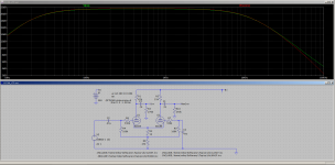
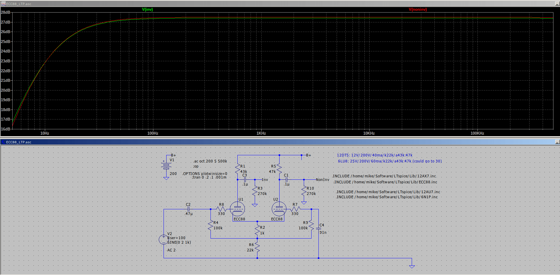
Just thought I would show what fixing the stoppers did to the sim. The interesting thing is that even at this low B+ of 200V with only 80V cathode to plate the simulated distortion at 24V peak output per phase has the primary distortion component down 55dB. With 100V or more on the plates it drops to 60dB down. Droping that output to 12V peak which is still more than enought to drive an EL84 drops the distortion simulation by at least 15 to 20dB. ECC88 might just turn out to be a pretty good LTP. I intend to try it some day.
Attachments
Uhh, why is the low frequency so limited?
What would happen to the frequency response when you simulate and use a 12AX7 / ECC83 ?
What would happen to the frequency response when you simulate and use a 12AX7 / ECC83 ?
Last edited:
Because C4 = 91 nF is a bit small. You might be better off to use the same value for C4 as for C2 (470 nF), which would give a cut-off of about 3 Hz (before the output/coupling RC).Uhh, why is the low frequency so limited?
Thank you, i didn't noticed that that C was so small.
But still remains the question what happens if i should use a 12AX7 / ECC83.
I had some bad experience with them (very limited high frequency)
But still remains the question what happens if i should use a 12AX7 / ECC83.
I had some bad experience with them (very limited high frequency)
Last edited:
Extended HF response needs more current. That equates to a low impedance circuit where an AX7 & similar tubes do not do well.Uhh, why is the low frequency so limited?
What would happen to the frequency response when you simulate and use a 12AX7 / ECC83 ?
All in the physics, not anything surprising.
I am not sure that -3dB at 12Hz is all that bad but mbrennwa is correct by increasing C4 you can get whatever f3 you want.Uhh, why is the low frequency so limited?
What would happen to the frequency response when you simulate and use a 12AX7 / ECC83 ?
At the original B+ (with cathode and plate resistors adjusted) 12AX7 distortion seems to run about 10dB higher at 24V peak output. Naturally increasing b+ will help because the AX7 is not fond of low plate voltage. With the right supply voltage and bias it looks like you could get similar (maybe still a little behind the ECC88) results but obviously with less drive capability. The high frequency response is somewhat less for the AX7 but still plenty good out to well beyond what any OPT can do (flat to around 300kHz).
So it appears that the ECC88 is especially attractive in amplifiers where the B+ is limited either by available transformers or output tube bias conditions or where good drive capability is desired without the addition of an extra drive stage.
This can be cured by increasing the value of R4 and R9 by a factor of 10, I'd say.Uhh, why is the low frequency so limited?
Best regards!
Y
I tried to make the first stage of this schematic: https://www.diyaudio.com/community/threads/cascoded-12ax7-ltp-stupid-good-performance.379589/page-7 and i was not satified with the frequency response of the first stage so i was wondering what will only the first stage do in spice?
I am interested in what spice will do versus real measurements
Yes i am aware of that.Extended HF response needs more current. That equates to a low impedance circuit where an AX7 & similar tubes do not do well.
All in the physics, not anything surprising.
I tried to make the first stage of this schematic: https://www.diyaudio.com/community/threads/cascoded-12ax7-ltp-stupid-good-performance.379589/page-7 and i was not satified with the frequency response of the first stage so i was wondering what will only the first stage do in spice?
I am interested in what spice will do versus real measurements
Last edited:
ECC83 is not good for any hi-fi LPT.. only if is loaded with some follower then ok.. if is loaded with some capacitance of next stage (output tube) from 100pf-1nF then is clear why. current to charge this capacitance must be significant, so tubes with low anode resistors ECC88, 5687, 6CG7,or russian 6N1P, 6H30 , 6n6p can be used for LTP with higher freq. result than ECC83
Good point on the capacitance. That is kind of what I was getting at with the lower drive capability. So you could use the AX7 but would really need a follower or other drive stage that can handle the output tube grid load.ECC83 is not good for any hi-fi LPT.. only if is loaded with some follower then ok.. if is loaded with some capacitance of next stage (output tube) from 100pf-1nF then is clear why. current to charge this capacitance must be significant, so tubes with low anode resistors ECC88, 5687, 6CG7,or russian 6N1P, 6H30 , 6n6p can be used for LTP with higher freq. result than ECC83
ECC88 with 270V B+, 25k and 27k anode resistors, 510 ohm cathode resistor and 20k tail looks pretty good driving a 270k grid leak and 1nF input capacitance gives f3 of almost 40kHz and good distortion at 24V peak swing each phase with about 5.3mA current through the tail.
now you can change tube to one level stronger with 10-15mA per anode , reduce anode resistors to 10k per example and see the new situation 🙂
100k is your target..
100k is your target..

- Home
- Amplifiers
- Tubes / Valves
- LTP frequency response