i am looking for advice / guidance regarding ltp degeneration amounts.
is it circuit / topology specific? is it just a designers choice?
what considerations need to be taken into account for choosing the degeneration amount?
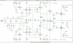
in the attached cct, i currently use 9.5 : 1 degeneration. is this too much - too little?
is it circuit / topology specific? is it just a designers choice?
what considerations need to be taken into account for choosing the degeneration amount?
in the attached cct, i currently use 9.5 : 1 degeneration. is this too much - too little?
Attachments
higher degeneration = higher linearity, lower transconductance and higher noise
10:1 is just fine
For more details, see the usual textbooks about amplifier design (Self, Cordell, Kolinummi)
10:1 is just fine
For more details, see the usual textbooks about amplifier design (Self, Cordell, Kolinummi)
P.S: Basically it is up to you, but LTP degeneration will affect amplifier stability by changing transconductance so if you change degeneration, you will also need to change compensation.
For current mirrors, higher degeneration lowers noise and increases output impedance.
For current mirrors, higher degeneration lowers noise and increases output impedance.
yes, i am looking for some calculated examplesFor more details, see the usual textbooks about amplifier design
came across this old thread....
https://www.diyaudio.com/community/threads/degeneration-resistors-in-long-tailed-pair.215846/
but no specific case worked examples so far.
https://www.diyaudio.com/community/threads/degeneration-resistors-in-long-tailed-pair.215846/
but no specific case worked examples so far.
If you look at this document, it will show you how to do it for a VFA via simulation from page 23 to 26.
https://hifisonix.com/wordpress/wp-content/uploads/2011/03/The_e-Amp_V2.03.pdf
The main reason for degenerating the LTP is to ensure it does not enter the nonlinear region with fast rise time signals (if it does, you are likely to get slewing induced distortion) - but there are a lot of trade-offs that make a simple mathematical formula less informative than a simulator.
Here is the formula for calculating Rdegen for a VFA from an article I wrote about CFA's and VFA's a few yrs ago (you will have to rearrange the formula to extract Rdegen)
Last edited:

believe it or not, i have been looking at your e-amp write up!
after reading "Slew Rate, Tail Current, Front End Overload and Input Filter" section several times, i have a few questions:
1) i was initially confused about the linear range offered by degeneration of +/-0.6V, as it seemed much smaller than then input signal quoted of 1.27v(rms?), however if i now understand correctly, you a refering to the LTP's "output error voltage" range and not the actual input to the amp.
2) you have used degen of 20:1 and state this gives a linear operation of +/-0.6V, does it then follow that 10:1 degen will offer +/- 0.3v of linear operation?
1. Yes - the linear range is about the linear range of the LTP pair and not the input voltage. The linear range is controlled by the amount of degeneration (Rdegen + re') which in turn is linked to the LTP current AND the input filter cut off frequency. So, if you had no degeneration and just relied on re' (the internal emitter resistance of the transistor), you would have to either set the LTP current relatively high and/or limit the input signal bandwidth in order to prevent slewing distortion. So, quite a few tradeoffs to make.
2. When you reduce the degeneration to 10:1 by making the emitter degen resistors c. 50 Ohms (they were 100 in the original e-amp design) you will essentially increase the open loop gain by c. 6dB and reduce the linear operating range of the diff pair by not quite 2x because re' now makes a larger contribution to the overall degeneration (5.2 Ohms with 100 ohms degen to 5.2 ohms with 50 ohms degen). In this case, in order to prevent slewing distortion, you can reduce the input signal BW using the model I showed in the e-amp write-up to keep the worst-case differential signal to within +/- 0.3V
(Note in the formula above I showed the term (0.026/(2*Iltp) - it should actually be just .026/Iltp. This is effectively the peak gm. If you use 0.5*Iltp, this will give you the gm at the central part of the transfer curve where the transistors share the LTP current equally. Note that gm changes over the operating range of the input pair and has been pointed to as a cause of 'phase intermodulation distortion' - see Robert Cordell for more information. I modern VFA amps with high loop gains, it's not considered an issue)
hi bonsai,
regarding "Figure 4 - Front End Model", i would like to try out my values to generate some graphs as per "Figure 5 - Input Stage Linearity Range"
do you have a ltspice circuit for this handy? the image in the write-up is a bit fuzzy.
regarding measuring the LTP's error signal in ltspice, is it simply to probe both the bases of an ltp and subtract one from the other?
Hi, I’ll regenerate the model tomorrow and put it up - I did that 10yrs ago so doubt I have the original LTSpice file.
yes - you subtract the voltages as you say and make sure the differential on fast rise times falls within the linear range of the diff amp, but you can also monitor the LTP output currents to make sure they do not switch off.
Note, you must do the fast rise time test with a full amp sim because you have to look at this in the closed loop condition. For the linear operating range of the diff amp, you can do this with just the diff pair. 21
Here is the LTP model - I manged to find it
This is the LTP linear range with Rdegen stepped from 1 Ohm to 101 Ohms in 20 Ohm increments. with no external degeneration, the linear range is very narrow (the centre two 'wungs') and with 100 Ohms, its c. 1V. note you can also use the LTP tail current to alter the slope - so increase the tail current allows you to reduce Rdegen but still maintain the same linear operating region.
I'll try to dig up the complete closed loop model later today.
Attachments
with the default values in the .asc file above, the linear range for 100R degen is approx +/-1.2v as shown in post 11.
i changed some of the values to reflect your your e-amp cct, and i was expecting linear range of +/-0.6v as per the write-up graph, but still around +/-1.2v🤔
(i want to be on the right track before plugging in values reflecting my own cct)
i changed some of the values to reflect your your e-amp cct, and i was expecting linear range of +/-0.6v as per the write-up graph, but still around +/-1.2v🤔
(i want to be on the right track before plugging in values reflecting my own cct)
Thats because I used a 5mA tail current. If you use a 10mA tail current the result is c. +-1.2V and with 5mA about half that. I would not use tail currents of > 10mA because base current errors then start to become an issue and you have to keep the feedback resistor values low, but that will cause other issues. So, 10mA is the practical upper end for the tail current, and 5mA a good compromise.
I would not lose any sleep over whether its 0.6V or 1V - anything above 0.5V is good, just make sure with your closed loop fast rise time tests the input stage currents do not go to zero - this indicates the LTP has switched and that means the amplifier is slewing. as mentioned earlier, the way to control this is to set the input filter cut off frequency appropriately.
I'll try to put up a model in the next day or so that you can play with to see how these parameters interact.
🙂
This is very interesting. I discovered Hifisonix/Ovation/Bonsai/Andrew a few days ago and started looking at published material (collecting) and have busy days ahead of me, I came for Feed Forward Error Corrections and are staying for many others 😉 but back to the topic of degeneration.
I have a question or two for Bonsai at the end.
Like many others here at diya.com, Nelson Pass is the guru and for many reasons, and something that stood out as I was going over the various FirstWatt/PASS LABS amplifiers, were the move from source degeneration as used on the XA.5 series to parallel common degeneration bias resistor used on the XS, XA.8 series and the XA25. To my knowledge and as far as I can tell, and I might have missed some prior publications, the only place that mentions not using degeneration is a positive feedback article covering the XA25 amplifier (see further down). I've been fortunate to have viewed the universal gain stages used in the pre- and power amplifiers and a few things set them apart.
What's interesting to me is the use of gain stage CCS and DC-servo only for the XS preamplifier, this could have easily been used in the remaining gain stages. But that is besides the point. So now that we know which platform uses degeneration and not, lets take a look at what N. Pass is saying about degeneration.Preamplifiers.Power amplifiers.
XA25: There are several unique things about the amplifier that make it a departure from the rest of the Pass Labs amplifiers. It's a fundamentally very simple topology made special by new parts and a unique approach to operating them in Class A without degeneration in the circuit (simplified circuit shown below). Years ago, we discovered that degeneration - that is to say placing resistors in series with FET source pins (or emitter pins for bipolar transistors) - has an impact on the sonic performance.
My late business partner Joe Sammut was adamant about the qualitative difference, and could spot it in blind testing, so I took it seriously. The difficulty comes the fact that there is a reason why people use degeneration (the "other form of feedback") in gain stages—it stabilizes the characteristics of the parts so that you don't have to do precise matching and compensation to keep circuits stable. At the same time, it acts like the feedback it is. Routinely, your "no feedback" solid-state amplifiers depend on degeneration in the gain stages to control the performance, and so it does not achieve all the goals that make SET tube amps attractive.
For those sonic reasons there have been several efforts at operating bipolar transistors undegenerated, and while the benefits have been noted, they have been accompanied by reliability issues. No need to mention names...
I set removal of degeneration from power amps as a design goal and over the course of several years came up with a couple of reliable techniques that are employed for the first time in the XA25. The result is better dynamics and more "life" to the sound, and with power FETs it turns out that there are a couple more advantages that you don't see with bipolar transistors.
Your basic FET character is "square-law," where the current through the device is a square function of the voltage across the control pins, the gate and the source. In this regard, the FET is very much like a tube.
It turns out that push-pull Class A operation of square law devices can result in intrinsic cancellation of distortion to literally mathematical zero. Unfortunately, degeneration in the circuit introduces distortion to that arrangement.
So basically, when Pass got rid of degeneration, the amplifier presented "better dynamic range". Comparing XA25 to XA30.8 and independent reports talk about the XA25 sounding a bit more open and have more detailed compared to XA30.8 as an example. Remember, both are class A. One thing that is used in the .8 series gain stage and not on the XA25 is the harmonic generator section in the gain stage. Basically, the .8 is SuSy with the addition of "H2 harmonic generator". And all of this in an effort to mimic tube performance.
Now for my questions.
- Is there a significant difference replacing degeneration with CCS or simply not using degeneration? ... watched one video showing the effects of bias resistor vs CCS and the noise floor dropped a whole order of magnitude.
- Do you have any experience not using degeneration and its affects on soundstage etc. ?
Member
Joined 2009
Paid Member
Member
Joined 2009
Paid Member
For me, the big tradeoff with LTP degeneration is the reduction in the open loop gain of your amplifier and this affects the distortion of the amplifier. With a Class AB amplifier you will usually get the lowest distortion by preserving OLG and limiting the degeneration to 10R to 20R.
In some designs, there's so much OLG available that it may make sense to run the LTP with higher degeneration, even up to 100R.
In all of my designs and projects I don't think I've ever gone that high, usually closer to the lower end of the range.
In some designs, there's so much OLG available that it may make sense to run the LTP with higher degeneration, even up to 100R.
In all of my designs and projects I don't think I've ever gone that high, usually closer to the lower end of the range.
- Home
- Amplifiers
- Solid State
- LTP degeneration