Interesting. I wonder how well MOSFETs do as low-EMI/RFI devices in rectification? Over-voltage/spike protection would seem essential, as a TVS is recommended.
There should be no problem with over voltage once a big capacitor is connected across the DC end of it. The spike will just get shoved into the capacitor and if a film capacitor is also added across the main smoother it will look like a short up to the peak pulse currant the FET can take. They should run cool as the volt drop across the FET will be less than a diode at normal working load.
Not sure if suitable for power ampl supplies.
The rectifier fets must have the same ratings and similar specs as the output fets or transistors of course.
Same SOA and heatsinking too.
If the outputs are paralleled then the rectifier ditto.
If the outputs have drivers then the rectifier ditto.
That is, it is not going to scale upwards nicely or simply or more economically. In fact I have never heard of a problem of heat in those 25A metal case bridge rectifiers that we tend to use, so why bother?
And for low current applications, also why bother?
If you need extra output voltage it is much easier to add another 5 turns of secondary winding or use low forward drop diodes or select the correct transformer in the first place.
Same SOA and heatsinking too.
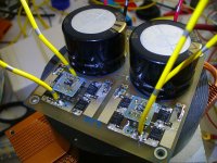
NOPE, it does not need any heatsink
it much COOLER than normal MUR1560 rectifier that i use for F5 (with heatsink)
41 Deg Celcius vs 73 deg Celcius (with 1.4 A each channel BIAS) ==> it means a lot to me 🙂
Attachments
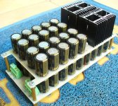
That photo is impressive.
So about heat. My logic was that the RMS current consumed by the amp, including the output, is the same RMS current that flows in the rectifying fets or diodes for that matter. Thinking about it, I did not take enough consideration of the mode, the rectifier is either fully on or fully off, the outputs are linear. Oops!
However my negative feeling about complexity remains.
The theory is that a diode will be heated by working currant multiplied by forward voltage in watts.
A FET driven by a square wave from the chip will be heated by the currant multiplied by itself and then by the on resistance.
The on resistance of FETs is getting lower every time a new part number is issued. These things now pay for themselves quickly in power savings.
Take a FET with an on resistance of 0.1 ohms and blast it with 10 amps. It will be heated by 1 what.
Take a power diode with a forward voltage of 0.6 volts and blast that with 10 amps and you get 6 whats of heat.
Do have a look at the data sheets in order to work out the power consumption of the parts you have already got.
The theory is that a diode will be heated by working currant multiplied by forward voltage in watts.
A FET driven by a square wave from the chip will be heated by the currant multiplied by itself and then by the on resistance.
The on resistance of FETs is getting lower every time a new part number is issued. These things now pay for themselves quickly in power savings.
Take a FET with an on resistance of 0.1 ohms and blast it with 10 amps. It will be heated by 1 what.
Take a power diode with a forward voltage of 0.6 volts and blast that with 10 amps and you get 6 whats of heat.
Do have a look at the data sheets in order to work out the power consumption of the parts you have already got.
Sorry you forgot to square those Amperage
so with 10Amp (0.1Ohm RdsOn) ==> 10 Watt dissipation
MOSFET with RdsOn lower than 20mOhm (high current) is easy to get, even in my country
Right now im using 3.1mOhm RdsOn MOSFET 🙂
Well spotted. I have seen electric power steering FETs with very low on resistances that would work very well up to about 60 or 70 volts in that circuit.
Some interesting data:
http://www.linear.com/docs/43273
http://www.linear.com/docs/43295
http://www.linear.com/docs/43332
Not cheap at all: 🙁
DC1823A - LINEAR TECHNOLOGY - DEMO BOARD, IDEAL DIODE CONTROLLER | Farnell Deutschland
Invalid Request
Where to get PCBs or even stuffed boards at a reasonable price?
http://www.linear.com/docs/43273
http://www.linear.com/docs/43295
http://www.linear.com/docs/43332
Not cheap at all: 🙁
DC1823A - LINEAR TECHNOLOGY - DEMO BOARD, IDEAL DIODE CONTROLLER | Farnell Deutschland
Invalid Request
Where to get PCBs or even stuffed boards at a reasonable price?
Ideal PSU
Although the efficiency gain isn't massive especially at high voltages it does look like a nice way of doing a linear supply compared to a diode bridge. It will never match the efficiency of a SMPS (due to copper losses in the transformer) but its much simpler to build and potentially lower noise.
I'm thinking about designing a PSU using this chip. I would probably design it for +ve and -ve rails up to 72v DC output.
I could also design in transformer soft start using effectively solid state relays (giveing the added bonus of active switch on / off. Of course it could be build up with different components for lower voltage or without the soft start for smaller transformers.
By the way the chip is available in DIP8 package so would be easy to solder. The PCB could be designed with through hole, or just large surface mount components if prefered.
Does that sound interesting to anyone?
- Home
- Design & Build
- Parts
- LT4320 active rectifier