my intention ' to replace the various integrated circuits of the series 78XX , with micro circuits to three feet ( in - gnd -out ) containing l ' lt3080est ( SMD version ) , a trimmer to adjust and two capacitors.

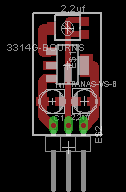
this is the micro pcb..
what do you think?
this is the micro pcb..
what do you think?
price
the price for a full assembled is 6eu.my intention ' to replace the various integrated circuits of the series 78XX , with micro circuits to three feet ( in - gnd -out ) containing l ' lt3080est ( SMD version ) , a trimmer to adjust and two capacitors.
this is the micro pcb..
what do you think?
I like the idea. Why don't like the 7805? How real is the 1.1Amps? That's a pretty small package. Surely the thermal coefficient is not very high.
Sent from my GT-I9505 using Tapatalk
Sent from my GT-I9505 using Tapatalk
I like the idea. Why don't like the 7805? How real is the 1.1Amps? That's a pretty small package. Surely the thermal coefficient is not very high.
Sent from my GT-I9505 using Tapatalk
The LT3080 is a 1.1A low dropout linear regulator that can
be paralleled to increase output current or spread heat in
surface mounted boards. Architected as a precision current
source and voltage follower allows this new regulator
to be used in many applications requiring high current,
adjustability to zero, and no heat sink. Also the device
brings out the collector of the pass transistor to allow low
dropout operation —down to 350 millivolts— when used
with multiple supplies.
A key feature of the LT3080 is the capability to supply a
wide output voltage range. By using a reference current
through a single resistor, the output voltage is programmed
to any level between zero and 36V. The LT3080 is stable
with 2.2µF of capacitance on the output, and the IC uses
small ceramic capacitors that do not require additional
ESR as is common with other regulators.
the circuit measure 1cm x 2cm
I can read data sheets too.
36 volts in and output set to say 5 volts and your load is 1/2 amps, your board will disapate 15.5 watts.
What purpose do you have for the little regulator. I see it usefull for dropping 5v down to 3.5v.
Sent from my GT-I9505 using Tapatalk
36 volts in and output set to say 5 volts and your load is 1/2 amps, your board will disapate 15.5 watts.
What purpose do you have for the little regulator. I see it usefull for dropping 5v down to 3.5v.
Sent from my GT-I9505 using Tapatalk
this system and ' was designed to obtain the best performance in conditions of low output current otherwise need a heat sink , or another type of stabilization system .I can read data sheets too.
36 volts in and output set to say 5 volts and your load is 1/2 amps, your board will disapate 15.5 watts.
What purpose do you have for the little regulator. I see it usefull for dropping 5v down to 3.5v.
Sent from my GT-I9505 using Tapatalk
logically if you have to get 5 volts output , 1/2 ampere , you can not put 36 volts input ...... but you have to put 7-9volt
You still haven't said what your intention is with these. The are not a universal 78 xx series replacement. The sot-223 case has a high temp coefficient (62 degree C /w) on large pcb (2500mm2). Your little board will have a higher temp coefficient.
You mention being able to parallel outputs but didn't bring the set pin out to bus togeather.
Maybe your use will be ok. I can see a few scenarios where these may be useful, but a universal replacement they are not.
Sent from my SM-N9005 using Tapatalk
You mention being able to parallel outputs but didn't bring the set pin out to bus togeather.
Maybe your use will be ok. I can see a few scenarios where these may be useful, but a universal replacement they are not.
Sent from my SM-N9005 using Tapatalk
the upgrade with this micro LT3080 is only necessary in circuits not demanding that draw little current .
a small heatsink can be installed behind the pcb so you can substitute any 78xx ic.
a small heatsink can be installed behind the pcb so you can substitute any 78xx ic.
layout
other productions are similar to this , I have changed the layout of the PCB , and I added a trimmer to adjust the output voltage , so ' can' be used as a regulator in other circuits.
other productions are similar to this , I have changed the layout of the PCB , and I added a trimmer to adjust the output voltage , so ' can' be used as a regulator in other circuits.
This reg needs a minimum load current otherwise it puts out full input voltage. Just a "power good" green LED with series resistor is enough to make it work as intended. Normally a load is present but adding the pads costs nothing.
Old thread.... probably the idea was never realized...
* a copper plane/copper pour at the other side of the board "stitched" (= plated through holes) to the other side at the chips "out" pin can function as heatsink. The way it was designed will get one in trouble with heat as a heatsink is absent.
Last edited:
- Status
- Not open for further replies.
- Home
- Group Buys
- LT3080 EST micro circuit