According DS maximum input/output voltage difference is 35V, but what is maximum input voltage? Can I use 60V input voltage for 25V output voltage? There is no information about absolute maximum input voltage.
There is no max input spec, you just must be sure not to exceed the max input-output difference.
There lies the rub though, when you switch the regulator on with a discharged cap at the output, it will take time for the output to rise. So at the start, the output is zero, and the input may be higher than the allowed input-output difference. The remedy is to put a zener from input to output so that the output cap can be charger through the zener without exceeding the input-output difference.
Jan
The non-military versions are only specified up to 25 V to 30 V Vin - Vout.
The LT1083 only sees the voltages between its pins. So in theory, 50 V in and 25 V out is fine, as is 1000 V in and 990 V out. However, the further you go above 25 V or 30 V, the more careful you will have to be with start-up, shut down, tolerances et cetera. Also keep in mind the second plot on page 7 and the required heatsinking.
The LT1083 only sees the voltages between its pins. So in theory, 50 V in and 25 V out is fine, as is 1000 V in and 990 V out. However, the further you go above 25 V or 30 V, the more careful you will have to be with start-up, shut down, tolerances et cetera. Also keep in mind the second plot on page 7 and the required heatsinking.
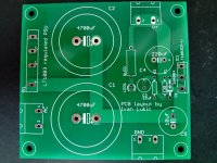
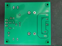
I intend to use it for a single supply amplifier working at 50VDC. If I use just a few Volts more at the input, say 53VDC, voltage difference will be just 3V. But I still need zener between input and output. Should I use, say 25V zener? Since my PCB has footprint for 1N4004 between input and output, can I use zener instead of it? Should it be oriented the same way as footprint for 1N4004? See pics attached. PCB uses ground plane at the bottom layer. Bridge rectifier and LT1083 are oriented with their heatsink sides towards edge of PCB so chasis can be used as heatsink if you bend pins and put PCB over pins. There is adj pin cap for additional noise suppression.
Attachments
Last edited:
You can use a zener in the same orientation, I think you could work that out yourself, you know what it has to do. Don't cut it close with 25V, use a 20V or 18V zener, in operation the input-output difference will anyway be much smaller.
Make sure you use a zener that can handle a several amps surge current, and don't go overboard with capacitance on the output. A lot of output capacitance doesn't serve any purpose and only makes the zener job harder.
Jan
Make sure you use a zener that can handle a several amps surge current, and don't go overboard with capacitance on the output. A lot of output capacitance doesn't serve any purpose and only makes the zener job harder.
Jan