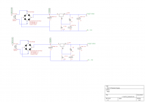
I've never had a linear regulator simply not start into a load. Here are two circuits. Top circuit has a bypass cap (C3) 470uF and the bottom circuit has a bypass cap (C3) of 47uF. The top circuit will NOT start a GM70. It puts out about 2 volts although it is set to put out 19.8V. It will put the 19.8 volts into a 6.8 ohm resistor, but cold the GM70 is only 1.6 ohms. The bottom circuit starts up like a champ. I was just using caps I had lying around. Thought I would share.
Attachments
but cold the GM70 is only 1.6 ohms.
Will it start with a 1.6ohm resistor?
I'd guess you're tripping the built-in short circuit protection.
(I'm assuming this reg has it built in,along with thermal,etc protections)
Your issue is with C3. As you stated yourself, it works when C3=47uF and not when C3=470uF. The ADJ cap is not supposed to be any larger than 25uF when R1=120R. With a 120R, your ADJ current is only 100uA.
See the datasheet for more info.
See the datasheet for more info.
Ya I read that in the data sheet, but I took that to mean @ 120Hz your Cadj should be at least 25uF. Earlier in the data sheet it says if you use 150uF aluminum on the output it will cover ALL CASES of bypassing the adjustment pin. Should say almost all cases.😉 But starting into a tube filament is probably a special case. You could never run this thing with 1.6 ohms continually at 20V. That would be 12.5 amps. I suppose I got a tad carried away with the 470uF cap, which can only charge as you said with the 100uA adjust current.
I have related problem in this topic:
http://www.diyaudio.com/forums/chip-amps/154975-lm3886-works-few-seconds-then-shut-off-7.html
Maybe someone from here willl help me...
In addition the Voltage on reference resistor R1 is 0.3V instead of 1,25, and on R2 is like on output ~ 3,5V. If i disconnect LM the Supply recovers to 22V.
I think is something with Overload Recovery?
From Linear: The circuit design used in the LT1083 family requires the
use of an output capacitor as part of the device frequency
compensation. For all operating conditions, the addition of
a 150μF aluminium electrolytic or a 22μF solid tantalum
on the output will ensure stability. Normally, capacitors
much smaller than this can be used with the LT1083. Many
different types of capacitors with widely varying characteristics
are available. These capacitors differ in capacitor
tolerance (sometimes ranging up to ±100%), equivalent
series resistance, and capacitance temperature coeffi cient.
The 150μF or 22μF values given will ensure stability.
If you only have 10uF on the output try 150uF as recommended. It says "normally" smaller caps can be used but I would think 10uF Aluminum would be right at the margin.
Edit: I may have mis-understood. What value do you have on the output?
Last edited:
For a filament regulator you don't need ANY capacitor on the ADJ pin as the regulator noise is superfluous and the ripple voltage is so small.
For any other application, the capacitor on the adjust pin reduces regulator noise, but also impairs transient response.
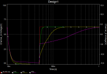
Lastly -- with 470u on the adjust pin you've made a nice slow-start regulator.
For any other application, the capacitor on the adjust pin reduces regulator noise, but also impairs transient response.
Lastly -- with 470u on the adjust pin you've made a nice slow-start regulator.
Attachments

For a filament regulator you don't need ANY capacitor on the ADJ pin as the regulator noise is superfluous and the ripple voltage is so small.
For any other application, the capacitor on the adjust pin reduces regulator noise, but also impairs transient response.
Lastly -- with 470u on the adjust pin you've made a nice slow-start regulator.
I removed the 10uF capacitor from the adjust pin and its working!
Nice graph I understand it now. Should I leave it without the capacitor or insert there 1uF - supposly will work also, what do you recomend?
Thanks a lot !
I use the cap on the reference pin because I need the additional ripple rejection.. Note that 120 ohms results in a reference current of slightly greater than 10mA - the voltage between Out and Vref is 1.25V approximately.
The very low cold resistance of the GM70 causes the regulator to go into fold back current limiting, this is likely with a large input to output voltage delta with high load currents at start up. One of the most reliable solutions I have found is to bypass about 1/3 of the filament current around the regulator using a paralleled power resistor between the input and output pins of the regulator.
In some cases a high current Schottky diode (= > 5A rating) in series with the output will allow the regulator to start.
I've also found the use of a NTC thermistor in series with the rectifier effective as it slows the input voltage rise sufficiently that the current limit is not tripped.
This problem is quite separate from stability considerations.. A very long delay on the Vref terminal would also help, but make sure to use the diodes found in older applications for the LM317 to protect the Vref terminal from excessive currents flowing through the Vref pin when power is removed deliberately or accidentally.
I suspect it doesn't work with 470uF because its leakage current is high and the current is passing to ground instead of to the regulator.
Do you think in amplifier power supply application LT1083 needs a additionaly protection diode?
Last edited:
Depends on the size of your capacitors - see the datasheet. That said, given the cost of these extra diodes I think it would be stupid not to put them in 🙂
/U.
/U.
- Status
- Not open for further replies.
- Home
- Amplifiers
- Tubes / Valves
- LT1083 interesting startup problem