Hello Juma,
locally only 2sk246 /2sj103 are available.
is there any way the circuit in post 485 / post 636 above could be adapted to use these?
regards
prasi
locally only 2sk246 /2sj103 are available.
is there any way the circuit in post 485 / post 636 above could be adapted to use these?
regards
prasi
Gain settings help
What are aproximal the values of R6/R7 for getting voltage gain of about 3 or 4 (10- 15db gain) on LSK pre -BAF 2013?
What are aproximal the values of R6/R7 for getting voltage gain of about 3 or 4 (10- 15db gain) on LSK pre -BAF 2013?
Hi,
I'm trying to find appropriate schematic and make a diy pre. Initially I was considering:
Preamp ideas for F5
but maybe I should try this with current mirror:
LSK pre - BAF 2013
My power amplifier needs about gain=2x and has Zin=47kohm. I could have regulated +/-12V DC as power source.
I have got two matched pairs of SK170/SJ74 with Idss=9.87
I know I should select suitable R2..5 resistors (current mirror). Please advice me from what values I should start? Will it be ok to set gain about 2x if I select 680 and 220 ohm for R7/R6? Also if idss of jfets are almost equal do I need P1=10ohm treamer?
Regards,
Hi,
I've just build one channel of pre from #492.
I used SMD version of BJTs: BC850C/BC860C with hfe about 550 and trimmer 20 ohm between JFET sources.
I have an offset issue. I have turned the 20 ohm potentiometr P1 maximal to the left and received +0,7 V DC and can't decrease the offset more. I've measured P1 resistance on SJ74 source have 1,5 OHm and 19ohm on SK170 source.
The additional values I've measured:

Please advice what to do to minimize the offset.
Thanks and regards,
I've just build one channel of pre from #492.
I used SMD version of BJTs: BC850C/BC860C with hfe about 550 and trimmer 20 ohm between JFET sources.
I have an offset issue. I have turned the 20 ohm potentiometr P1 maximal to the left and received +0,7 V DC and can't decrease the offset more. I've measured P1 resistance on SJ74 source have 1,5 OHm and 19ohm on SK170 source.
The additional values I've measured:
Please advice what to do to minimize the offset.
Thanks and regards,
Hi Bern,
schematic in post 492 has no trimmer pot. You don't want it too. You got it matched all around. If you are sure that all your parts and connections are good, try to slightly vary the value of current mirror emitter resistors on one side (use 27R + 10R pot instead of 33 R) and see what you get... 😉
schematic in post 492 has no trimmer pot. You don't want it too. You got it matched all around. If you are sure that all your parts and connections are good, try to slightly vary the value of current mirror emitter resistors on one side (use 27R + 10R pot instead of 33 R) and see what you get... 😉
Thank you juma,Hi Bern,
schematic in post 492 has no trimmer pot. You don't want it too. You got it matched all around. If you are sure that all your parts and connections are good, try to slightly vary the value of current mirror emitter resistors on one side (use 27R + 10R pot instead of 33 R) and see what you get... 😉
I have reviewed my circuit and found a mistake...
I connected the Q8 transistor incorrectly. After resoldering Q8 and change R3/R5 from 33 to 27 ohm everything seems to work correctly. I set 20ohm trimmer to 11,79/10,88 ohm and have offest below 0,1mV. With R3/R5=27 ohm I have current through BJTs 12,68 and 12,70mA (before LEDs) and current through JFETs 7,53 and 7,46mA. I look forward to completing the second channel and real music testing🙂

anorher advantage of simple circuits - mistakes are easily found 🙂
Yes. Usually the simpler the better.🙂
juma do you think I should leave 47R in R2, R4 and 27R in R3, R5 or maybe it will be better if I change the R3, R4 resistor from 27R to 25R? Should I remove 20R trimmer (and insert 0ohm resistor or jumper)?
Regards,
Yes. Usually the simpler the better.🙂
juma do you think I should leave 47R in R2, R4 and 27R in R3, R5 or maybe it will be better if I change the R3, R4 resistor from 27R to 25R? Should I remove 20R trimmer (and insert 0ohm resistor or jumper)?
Regards,
I have built this circuit twice, once with the 20 ohm trimmer, another version without. Both had coupling caps on output. Identical parts were used, except one had dale resistors and one has takman metal films. My feeling is the version without the trimmer and the Takman films sounds more relaxed, less uptight. The trimmer may effect the harmonic content due to the balancing/cancelling involved. But I like both versions of the circuit.
It’s my favorite SS preamp.
I'm trying to get another preamp together using the Cubie2 boards that I obtained. Probably something temporary at first to compare to my current linestage (BA 2018). These have the JFET degen trick and well matched BJT's. Powered up and adjusted fine with a lab supply. Awaiting on parts for the Super Regulator boards from the Store, should be here soon.
Hi,
I completed build a circuit from #542. I treat JFET Source follower as an option and not have tested yet.
I tested only a standard version and sounds great to me. The sound is clear full of details with good space. I have trouble to find genuine BC550/560C BJT transistors so I used SMD versions: BC850C/860C. I needed balanced output so I use output transformer. Also I added two SE input selector and a few seconds delay circuit after switch-on. I used low noise voltage regulators LT3045/LT3094 set to +/-12V DC. Thank you juma.🙂
An externally hosted image should be here but it was not working when we last tested it.
Hi,
I'm going to build a second PRE based on #485.
This time I would like to apply two sources switch and at the same time a gain switch so in this way each source will have its own gain. I've made prototype.
I used two DPDT relays: one for source switching the second for a gain switch.
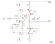
The R1, R15 resistors change the gain (see attached schematics).
When i switching sources/gains I am experiencing loud crackling noises from the speakers (even with minimum volume).
Is there any way to get rid of these unpleasant pops?
I'm going to build a second PRE based on #485.
This time I would like to apply two sources switch and at the same time a gain switch so in this way each source will have its own gain. I've made prototype.
I used two DPDT relays: one for source switching the second for a gain switch.
The R1, R15 resistors change the gain (see attached schematics).
When i switching sources/gains I am experiencing loud crackling noises from the speakers (even with minimum volume).
Is there any way to get rid of these unpleasant pops?
Attachments
Yes. Use "make before break" type of switch.
Thank you.
It is not easy to find 'make before break' relay.
Browsing the Mouser store's offer I have found only one 'form D' relay:
Fujitsu RY-12D-K
...Is there any way to get rid of these unpleasant pops?
...It is not easy to find 'make before break' relay...]
If you can't obtain one of the switches juma posted links for, there are a couple of alternatives that spring to mind:
1, My preferred choice would be to change the gain by having two different values for R21, if you use a break before make switch, the gain will drop to unity briefly when switching.
2, Leave R15 permanently wired in circuit and switch R1 in parallel to change the gain.
3, Use method 2 for option 1
- Home
- Amplifiers
- Pass Labs
- LSK pre - BAF 2013