When making speaker boxes and different set ups, crossovers seem to be where the biggest whole is in product selection. Getting just what you need for your specific application is difficult or impossible. So I figured I need to learn how to make them. Anyways, to my questions...
I got a program that will give me the LP/HP filter design for a set frequency & ohm load. Example...
I know I prolly' cant find capacitors and inductors with the correct rating to the 0.01 decimal point, but I figured to the tenth decimal point or so would be close enough. Problem is that when I am looking up these things I cant read the rating system correctly. Many say rated at like 220v, plus getting correct ohm rating of unit. 😕 Plus wiring these two set-ups parallel into a 4ohm load at the amp shouldnt change anything should it seeing the terminal load at the speaker is still 8ohms.
I got a program that will give me the LP/HP filter design for a set frequency & ohm load. Example...
An externally hosted image should be here but it was not working when we last tested it.
I know I prolly' cant find capacitors and inductors with the correct rating to the 0.01 decimal point, but I figured to the tenth decimal point or so would be close enough. Problem is that when I am looking up these things I cant read the rating system correctly. Many say rated at like 220v, plus getting correct ohm rating of unit. 😕 Plus wiring these two set-ups parallel into a 4ohm load at the amp shouldnt change anything should it seeing the terminal load at the speaker is still 8ohms.
This circuit has an actual input impedance of 8 Ohms. The crossover feeds only the woofer below 720Hz or the tweeter above 720Hz. At any given frequency, they aren't really in parallel.
You can safely round off the values:
29.47 uF = 30 uF
14.74 uF = 15 uF
44.21 uF = 45 uF
Inductors are fine as marked except 1.06mH can be 1.00 mH
Capacitor voltage ratings for this circuit should be 50V or more. Do not use standard electrolytic capacitors, you must use bi-polar types. Many people will pay extra for a film capacitor instead of an electrolytic because they tend to sound better.
Do you have any datasheets on the drivers you are using? The reason I ask is that very rarely will the crossover parts align with a textbook calculation for the rated impedance of the drivers. Even though it may be an "8 ohm" woofer, the impedance at for example 2500Hz may be 11 ohms or more! With datasheets of the impedance curves and frequency responses, we can at least get close to the crossover values needed. The caveat here is that the frequency response will depend on the enclosure in which the driver is used to some extent, and you will never really know what that is unless you measure the driver in the enclosure yourself.
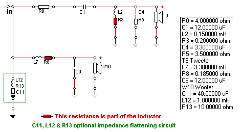
Let's do a case study of Zaph's popular new SR71 design here: http://www.zaphaudio.com/SR71.html
The crossover schematic looks pretty straightforward

You have what looks like a standard 2nd order electrical crossover topology. The tweeter circuit has two added components for top end response shaping (C4 and R5), and the green boxed components are optional for impedance flattening.
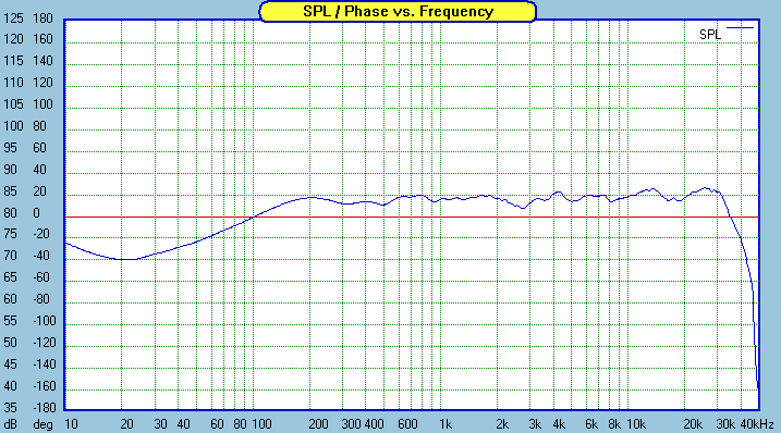
Here is Zaph's measured response:

Looking at the meat of the crossover: C1, L2, L7 and C9; lets compare what Zaph used to what is calculated from a textbook crossover calculator.
Using the calculator here: http://www.lalena.com/Audio/Calculator/XOver/
Inputting the rated impedance of the tweeter (6 ohms) and woofer (8 ohms); and inputting the crossover frequency (1750 Hz) and type (2nd order Linkwitz-Riley), we get the following values.
Related to the figure above, C1 would be 7.58uF, L2 would be 1.09mH, L7 would be 1.46mH, and C9 would be 5.69uF.
Here are the results plotted with Speaker Workshop.
This speaker, if built, would have absolutely no midbass or bass, and would have screeching high midrange and treble. So what happened?
The ER18RNX in this case has a rising response; to flatten this out requires more inductance than the textbook formula provides. Using the textbook inductor, the response of the ER18RNX stays at reference level until nearly 5kHz, where it drops off very sharply. There is a bobble in the phase response in this area as well, due to the ER18RNX having a cone mode with a peak at 5kHz. This causes the ER18RNX and the 27TDFC to be quite mismatched in phase and results in a suck out around 5kHz.
The larger than textbook inductor also provides Baffle Step Compensation (BSC) by beginning the electrical rolloff at a lower frequency, effectively boosting the bass and midbass. This is a trick that works well with woofers that have rising response, and is something that a textbook design would have difficulty implementing without much trial and error.
The 27TDFC in Zaph's design has been tuned to compensate for the woofers rising response and doubles to tilt the listening axis upwards to align it with the tweeter. The crossover rolls the tweeter off at a much higher acoustic slope by combining the natural rolloff of the tweeter with the electrical filter rolloff. The resulting inductor value is no where near what the textbook filter would recommend. It is nuances like these that make crossover designing both a science and an art.
I think you will find that textbook filters work best when the crossover frequency is more than an octave (double or half the frequency) away from the usable flat response of the drivers. Even then, it is still going to be hit or miss, with quite frankly more misses than hits.
A far better way to calculate the crossover frequency would be to use the free tools here: http://www.pvconsultants.com/audio/frdgroup.htm
If you need further help, feel free to ask!
Regards,
David
Let's do a case study of Zaph's popular new SR71 design here: http://www.zaphaudio.com/SR71.html
The crossover schematic looks pretty straightforward

You have what looks like a standard 2nd order electrical crossover topology. The tweeter circuit has two added components for top end response shaping (C4 and R5), and the green boxed components are optional for impedance flattening.
Here is Zaph's measured response:

Looking at the meat of the crossover: C1, L2, L7 and C9; lets compare what Zaph used to what is calculated from a textbook crossover calculator.
Using the calculator here: http://www.lalena.com/Audio/Calculator/XOver/
Inputting the rated impedance of the tweeter (6 ohms) and woofer (8 ohms); and inputting the crossover frequency (1750 Hz) and type (2nd order Linkwitz-Riley), we get the following values.
Related to the figure above, C1 would be 7.58uF, L2 would be 1.09mH, L7 would be 1.46mH, and C9 would be 5.69uF.
Here are the results plotted with Speaker Workshop.
An externally hosted image should be here but it was not working when we last tested it.
This speaker, if built, would have absolutely no midbass or bass, and would have screeching high midrange and treble. So what happened?
The ER18RNX in this case has a rising response; to flatten this out requires more inductance than the textbook formula provides. Using the textbook inductor, the response of the ER18RNX stays at reference level until nearly 5kHz, where it drops off very sharply. There is a bobble in the phase response in this area as well, due to the ER18RNX having a cone mode with a peak at 5kHz. This causes the ER18RNX and the 27TDFC to be quite mismatched in phase and results in a suck out around 5kHz.
The larger than textbook inductor also provides Baffle Step Compensation (BSC) by beginning the electrical rolloff at a lower frequency, effectively boosting the bass and midbass. This is a trick that works well with woofers that have rising response, and is something that a textbook design would have difficulty implementing without much trial and error.
The 27TDFC in Zaph's design has been tuned to compensate for the woofers rising response and doubles to tilt the listening axis upwards to align it with the tweeter. The crossover rolls the tweeter off at a much higher acoustic slope by combining the natural rolloff of the tweeter with the electrical filter rolloff. The resulting inductor value is no where near what the textbook filter would recommend. It is nuances like these that make crossover designing both a science and an art.
I think you will find that textbook filters work best when the crossover frequency is more than an octave (double or half the frequency) away from the usable flat response of the drivers. Even then, it is still going to be hit or miss, with quite frankly more misses than hits.
A far better way to calculate the crossover frequency would be to use the free tools here: http://www.pvconsultants.com/audio/frdgroup.htm
If you need further help, feel free to ask!
Regards,
David
Thanks for the info. Unfortunately a lot of what you say is over my head. I have read up a little, yet havent got to the point where I know enough about the science so that I can calculate according to impedance curves. I plan on getting to that point though. Just am kinda busy with other stuff at this time. I am saving all of the sites, I will read up on it.
But, for the time being I got a question for you. The 2/3 way cross over calculators at LaLena.com look helpful. If I run 3/2 8ohm speakers through these plans, these are designed to keep the impedance at 8homs (or which ever) on the channel? I know that the LP/HP filter design I have should drop my impedance if I wired multiple speakers to the same channel. And, how much will using L-Pads affect this. Think I should use an L-Pad before or after the crossover?
But, for the time being I got a question for you. The 2/3 way cross over calculators at LaLena.com look helpful. If I run 3/2 8ohm speakers through these plans, these are designed to keep the impedance at 8homs (or which ever) on the channel? I know that the LP/HP filter design I have should drop my impedance if I wired multiple speakers to the same channel. And, how much will using L-Pads affect this. Think I should use an L-Pad before or after the crossover?
- Status
- Not open for further replies.