Hi All,
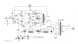
I’ve been looking to build yet another 6L6 amp. I came across Joel’s 6L6 PP design which has some nice specs. But also found Yves one which is also nice and has some more power output.
Anyway Joel writes in his documentation;
specs say 0.29% @ 10 W that looks pretty nice to me.
So I looked up the Radiotron Designers Handbook and finally found the graph he is talking about at page 570.
But it seems to me that when lowering to 3,5K the 2nd distortion is 5% the 3th is also 5% 4th would be 2% this is at 7,2 watts.
Because this numbers are different I am confused, can somebody explain to me how this works?
Another question;
Is the method of lowering the primary resistance as described usable for other 6L6 schematics? for instance Yves one, what would happen to the output power and distortion if I was to use a 5K instead of a 6K OPT?
I’ve been looking to build yet another 6L6 amp. I came across Joel’s 6L6 PP design which has some nice specs. But also found Yves one which is also nice and has some more power output.
Anyway Joel writes in his documentation;
“ The output tubes are biased into class A using the manual values of Ec –14V, Eb 250V, Ec2 250V. At these low plate and screen voltages, any of the 6L6 versions could be used: 6L6 (metal), 6L6G, 6L6GB, or 6L6GC, etc. The book value output transformer primary at this operating point is 5k p*p, but I chose 3.4k deliberately to lower higher order harmonic distortion. The Radiotron Designer’s Handbook, 4th Ed., contains a graph showing just such a decrease as the load resistance is lowered for a 6L6 at our operating point. The second harmonic climbs to over 12% as you do this, but is cancelled due to the push*pull operation. Meanwhile the 3rd harmonic has fallen from 3% at 2.5k to under 2% at a 1.7k load. This seems to give a good compromise between lowering the distortion, and the drop in output power.”
specs say 0.29% @ 10 W that looks pretty nice to me.
So I looked up the Radiotron Designers Handbook and finally found the graph he is talking about at page 570.
But it seems to me that when lowering to 3,5K the 2nd distortion is 5% the 3th is also 5% 4th would be 2% this is at 7,2 watts.
Because this numbers are different I am confused, can somebody explain to me how this works?
Another question;
Is the method of lowering the primary resistance as described usable for other 6L6 schematics? for instance Yves one, what would happen to the output power and distortion if I was to use a 5K instead of a 6K OPT?
Attachments
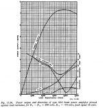
The distortion vs load graph is for SE 6L6, so it's about lowering from 2k5 to 1k7 as Joel writes.
The distortion vs load graph is for SE 6L6, so it's about lowering from 2k5 to 1k7 as Joel writes.
damn of course
 it's one half...
- Status
- Not open for further replies.