Yeah, whenever the 3-legged fuse's D-S fuses together the no-legged fuse de-fuses and saves the day.
Didn't know temperatures can turn NP into a Brit, an Aussie, an Irish, or a German...
Didn't know temperatures can turn NP into a Brit, an Aussie, an Irish, or a German...
Zen Mod, Looking around I now see the temperature derating chart telling me why. But when I look at the IRFP240 data sheet it only has a power dissipation multiplier chart. If I take the rated 150 watts at 100C is 0.4. 150w x 0.4 = 60w. I know the mica insulator slows the transfer of heat. What else causes the power rating to be lowered to around 50C at 50 watts?
well, I meant on nothing too much scientific ;
fact is that I know for several amps with 50W through IRF150 , with heatsink cruising at 50C , and they work flawlessly few years .....
if you can go lower with any or both of these figures - better .
fact is that I know for several amps with 50W through IRF150 , with heatsink cruising at 50C , and they work flawlessly few years .....
if you can go lower with any or both of these figures - better .
Update
Been gathering parts and I finally got everything to rebuild the power supply. Since the new parts would not all fit in the case I had to build a separate unit for them. I bought another 20Vct power transformer. I then opened each transformer up and split the center tap so I could wire them up with their secondaries in parallel. Now I have two transformers rated 10V@20A. Each transformer has its own bridge rectifier combined to make a dual rectifier for +/-12V and then connects to a 100mF capacitor. I used four .27ohm resistors on the rails between the first cap and the second 100mF capacitor. All four 100mF caps are each bypassed with a 1uF metalized film and 1.5nF C0G ceramic capacitor. An umbilical cable runs from the PS unit to the amp and connects to two 50uF ASC metalized film oil filled cans. The power then splits and runs to each channel. The wire gauges are 14awg for the + and - . I used 12awg for the grounds with two grounds wires running from the amp the the PS unit.
What I had been experiencing before was when instruments were panned hard left or right they would get holographic. But when the were panned in the middle, I could hear them in detail but not focused. I had thought that was because of the room being small. Now listening to the amp I realize that it was crosstalk between the channels that was smearing the imaging. The imaging in the middle is now as focused and holographic as the sides were. Truly an amazing improvement. I think most of the effect is from the very low resistance to ground path the amp now has. I ordered two more 50uF ASC caps to try to separate the channels more by running two umbilical cables to the amp. Each one connecting to a pair of ASC's and then to it's channel pcb.
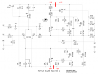
Next. I was reading lots of information from the PASSDIY site. Thank you for that site. I saw that it is recommended that IRFP240 are used for rails over 20V and IRFP044 for rails under 20V. Well I'm down at 12V so I ordered some IRFP044s to try. The other thing I read was in the BA2. It is recommended the jfets 2sj109 would like to see at least 18V. Well thats way down on my amp too. So I would like to get that up by splitting the power supply. I would like to have the front circuit (2sj109) at +/-24V and the back circuit (IRFP240) at +/-12V.
Is this possible or would it screw things up? The attachment shows red lines where I think the rails should be split.
Thanks
Scott
Been gathering parts and I finally got everything to rebuild the power supply. Since the new parts would not all fit in the case I had to build a separate unit for them. I bought another 20Vct power transformer. I then opened each transformer up and split the center tap so I could wire them up with their secondaries in parallel. Now I have two transformers rated 10V@20A. Each transformer has its own bridge rectifier combined to make a dual rectifier for +/-12V and then connects to a 100mF capacitor. I used four .27ohm resistors on the rails between the first cap and the second 100mF capacitor. All four 100mF caps are each bypassed with a 1uF metalized film and 1.5nF C0G ceramic capacitor. An umbilical cable runs from the PS unit to the amp and connects to two 50uF ASC metalized film oil filled cans. The power then splits and runs to each channel. The wire gauges are 14awg for the + and - . I used 12awg for the grounds with two grounds wires running from the amp the the PS unit.
What I had been experiencing before was when instruments were panned hard left or right they would get holographic. But when the were panned in the middle, I could hear them in detail but not focused. I had thought that was because of the room being small. Now listening to the amp I realize that it was crosstalk between the channels that was smearing the imaging. The imaging in the middle is now as focused and holographic as the sides were. Truly an amazing improvement. I think most of the effect is from the very low resistance to ground path the amp now has. I ordered two more 50uF ASC caps to try to separate the channels more by running two umbilical cables to the amp. Each one connecting to a pair of ASC's and then to it's channel pcb.
Next. I was reading lots of information from the PASSDIY site. Thank you for that site. I saw that it is recommended that IRFP240 are used for rails over 20V and IRFP044 for rails under 20V. Well I'm down at 12V so I ordered some IRFP044s to try. The other thing I read was in the BA2. It is recommended the jfets 2sj109 would like to see at least 18V. Well thats way down on my amp too. So I would like to get that up by splitting the power supply. I would like to have the front circuit (2sj109) at +/-24V and the back circuit (IRFP240) at +/-12V.
Is this possible or would it screw things up? The attachment shows red lines where I think the rails should be split.
Thanks
Scott
Attachments
....
Is this possible or would it screw things up? The attachment shows red lines where I think the rails should be split.
Thanks
Scott
just forget ;
12V is plenty for input Jfets , and splitting PSU is big no-no - because both biasing and modulation of (lower) output mosfet is referenced to negative PSU leg
regarding positive side - all you have on positive leg is CCS for input LTP , and you'll not gain anything altering voltage
I really like the direct coupling of these circuits so I was hoping there was a way to keep it. Well I am still going to split these circuits because I am going to experiment with lower rail voltages for the MOSFETs. And at some point the 2sj109 circuit is not going to be happy.
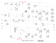
Attached is an idea that I think will work well. It uses a interstage transformer. The primary has around only 4mA going through it. That makes things easier getting a higher inductance. The secondary connects to a voltage divider between the ground and negative rail that sets the voltage for the MOSFET gates. The ratio is 2:1 which will give me a lower voltage out but will also give me more current out. That should help the MOSFET capacitance and give more bandwidth and lower high frequency distortions too.
I'm not sure if the negative feedback needs to be removed or not.
Scott
Attachments
nope
first reason is - servo function of input LTP is prevented
second reason ........ naah ......... just forget and go back to reading all pdfs from NP site(s) .
same concept I drew once ........ I'm not deleting that just to help me to stay humble
( OK - second reason is that proposed biasing of output is rough , and you can't do it that way - at least if you want to use your speakers for more than 10min)
Thanks Zen Mod.
I searched for more info and now I think I understand. Any DC offset at the output is sent to the 2sj109 thru the negative feedback loop. Q1b causes Q1a to changes its output to correct for the offset and send it to the MOSFETs.
So to split these circuits I would need to add a DC servo on the MOSFET side. And that would probably give better biasing also.
Is this correct?
Scott
correct ;
beauty of that amp is in simplicity ; it's easy to worsen it ;
Babelfish J is what I dared to complicate .....
beauty of that amp is in simplicity ; it's easy to worsen it ;
Babelfish J is what I dared to complicate .....
IRFP044 vs. IRFP240
The IRFP044 are suppose to like lower rail voltages so I wired them up and gave them a listen. They reminded me that when I originally built the Aleph J according to the schematic, it sounded very nice as soon as it was turned on. Through experimentation by lowering the rail voltage and increasing the bias I somehow had the IRFP240s sounding just ok when first turned on. For the first hour the amp sounded the same, detailed but not textured and flat with no depth. Around one hour the texture started to increases. The difference between 1 and 1-1/2 hours was from just ok to holographic imaging and 3D sound stage. The only thing that sucks is waiting 1 1/2 hours to settle in.
One time I tested the current every 5 minutes for the first 1/2 hour, then every 15 minutes while it warmed up. I tested the voltage across the CRC power filter resistors.
0-253.7mV
5-242.9mV
10-240.6mV
15-239.0mV
20-238.0mV
25-237.4mV
30-236.8mV
45-235.1mV
60-235.5mV
75-234.6mV
90-234.1mV
The readings varied from 233.9mV to 234.4mV for the next two hours after 90 minutes. So as the current stabilized the sound became amazing.
Back to now. The IRFP044s sounded very nice as soon as the amp was turned on. Very textured and liquid sounds but not holographic or 3D. The low end was VERY nice. It got fuller and deeper, something I really liked. It was not night and day difference, but noticeable. As I listened I kept waiting for the sound to go that little bit further to where the IRFP240s did. It never did though. I listened for the next week to the IRFP044s and was not sure if they were breaking in and sounding better or if I was just getting used to them. If I had never heard what the 240s sounded like, I would have been completely happy the way it was.
I was reading some descriptions of the differences between IRFP044 and IRFP240. They seemed to match my findings. The IRFP044s richer, fuller, deeper low end with not as high frequency extension. The IRFP240s thinner low end compared to the 044s but not thin sounding with more high frequency sparkle.
While listening to the IRFP044s I received my 2mH 12A chokes for the power supply. I had a CRC filter and wanted to make a LC filter that would lower the rail voltages from +/-12.1V to around +/-9V. The choke replaced four .27 ohm resistors with a total of .0675 ohm. I hooked them up and turned on the power. Hummmmmm. 120Hz coming from the speakers. Music played, just a loud hum too. The rails had dropped to +/-8.4V, more than I had expected. Reading around I think the hum was from radiating from the choke. I switch from a LC to a CLC and the amp was completely quiet. The rail voltage was now +/-12.2V. The difference between the resistors and choke was amazing. Everything was more focused and was starting to sound holographic and 3D. What I think is happening is the choke is blocking all the high frequency garbage in the power supply allowing the amp to reveal more fine texture.
Now I need to see what the IRFP240s sound like with the power supply mods. I hooked them up and turned it on. Right away they sounded like the 044s at their best. The low end was not as refined sounding but still very nice. The high end did have some more sparkle to everything. Then around 1-1/2 hours the amp turned completely holographic and the sound stage depth was amazing.
I don't think the lower input capacitance is responsible for the holographic abilities of the IRFP240s. I think it might have to do with the rise and fall times. The 204s are over twice as fast as the 044s.
IRFP240
rise 51nS
fall 36nS
IRFP044
rise 120nS
fall 86nS
Note. I now see that there is a difference between IRFP044 and IRFP044N. I am using the IRFP044Ns.
IRFP044N
rise 80nS
fall 52nS
Still faster but not as great a difference. And the input capacitance is lower for the 'N' version, 1500pF vs. 2500pF. So I am not sure what makes the IRFP240s sound so much better in my system then the 044s. The chokes made both the IRFP240s and the IRFP044Ns sound more refined then before. I really like the new combination.
Anyway I will have to try some of the other MOSFETs and see what they sound like.
Also I am going to try biamping and build a second amp for lows. For that I will be using the IRFP044Ns.
Scott
Power output question
Someone asked me what my amp's output is. I looked into it and found this way from another post here. Hook a function generator up to the inputs and send a sine wave into it. Disconnect the speakers and place a power resistor across one of the outputs. Hook a scope up across the resistor and measure the sine wave. Turn the sine wave up until you find the spot just before it clips. With this information you can figure what your output is in watts.
Here is what I come up with.
My scope says 20V p-p before clip.
Power resistor is 7.8 ohm.
That gives me 2.5A.
Divide voltage in half and multiply by current.
2.5A x 10V = 25W per channel.
Now this made me confused. I thought I would have around 10W max per channel. This much more then I expected. I guess it is because I have pushed the bias up to 2A through each Mosfet. (it makes it sound so good)
Also I thought the output Mosfets were dissipating 50W each. Now I think that it is 50W per channel and 25W per Mosfet. Correct?
This is what I get for the Mosfets.
Voltage across .3 ohm source resistor is 610mV = 2.03A
Rail voltage +/- 12.1V
12.1V x 2,03A = 24.56W each
24.2V x 2.03A = 49.12W per channel
What confuses me is the fact that the output seems to be half of the channel's power. Since class A amps are not 50% efficient so I figure my calculations are wrong somewhere.
Can anyone tell me what is incorrect.
Thanks
Scott
Scott
I think you need to use just Vpeak not p-p.
This will halve both your current and voltage used in the final calculation for a total of 4 reduction in average power (6.3W)
Hope this helps
-Antonio
I think you need to use just Vpeak not p-p.
This will halve both your current and voltage used in the final calculation for a total of 4 reduction in average power (6.3W)
Hope this helps
-Antonio
Thanks magnoman. 6.3W sounded much more like what I expected. Looking around here for more posts on the subject I finally found one that gives me close to that answer.
Connect a function generator to the amp input. Connect a power resistor to the output for a load. Connect a scope across the resistor. Send a 60Hz sine wave into the amp and turn up until just before the scope shows clipping. Take a multmeter set on AC and take a reading across the resistor. Take that reading and multiply by itself. Then divide by the resistor value for the output in watts.
Scope shows 20V p-p before clipping.
Multimeter shows 6.93VAC.
6.93V x 6.93V = 48V
48V / 7.8 ohm = 6.1W
That much better.
Scott
Input circuit adjustment problems
I'm having a some trouble adjusting the ccs and the differential input. After lowering the rails voltage I see the voltage across R8 is 8.52V instead of 8.3V and R7 is 5.15V instead of 4.3V like on the schematic. Also since I have lower rails, I can increases the current through the 2sj109 to get the same dissipation as the higher voltages. Original current was 8.4 mA @ R8 and 4.3 mA @ R7 with a dissipation of .152W @ Q1. With the lower rails I can increase the current to 26.6 mA @ R8 and 13.3 mA @ R7 with the dissipation .152 W @ Q1.
So I studied up on ccs and I understand the voltage drop across R8 is set by Z1 minus the Vbe of Q2. The value of R8 sets the current through the circuit.
At first I thought I would try to just lower R7 to get a lower voltage before I increased the current. But as I reduced R7 the voltage across it stayed the same. I kept lowering it until the voltage suddenly dropped to around 3V.
Then I decided to try to set R8 at 302 ohm and R7 at 314 ohm which should give me close to the currents I want. The new voltages were R8 8.66V and R7 5.15V. So 8.66V across 302 ohms is 28.7mA and 5.15V across 314 ohms is 16.4mA.
So things are not working as I thought they should. I there something about the input circuit that I do not understand? Do I need to adjust the current through Z1 by changing the value of R5?
Another thought was, could the current protection of the output circuit be affecting things?
Scott
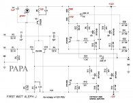
you just don't get how that circuit works
make it like this
make it like this
Attachments
Last edited:
Thanks Zen Mod. Looking at what you posted made sense. The LED would drop the voltage 2.1V minus .8V for Q2 = 1.3V. Then 1.3V across 150 ohm = 8.7mA. Split that in two for 4.35mA. That across 1k ohm = 4.35V.
So I pulled out Z1 and replaced it with a green LED. I bypass R8 (1k) with a 177 ohm resistor for a total of 150 ohms. I turned on the amp and the LED lit up. I check the voltages.
LED 1.94V
R8 1.32V
R7 5.19V 😕
Strange. So I pulled R7 out and checked with a multimeter which said 997 ohms. I replaced R7 and gave a listen. Sounds the same as the other channel. Still very nice.
Now I know something else is wrong and not just my math. Any ideas?
Scott
ref voltage for green led at 3-5mA is 1V93
Ube is , say , 0V65
so - you'll have 1V93 - 0V65 ~ 1V3 across R8
that means exactly what you wrote - ~ 4,35mA through each Jfet - but in ideal condition
LTP will correct currents through own halves , to maintain ( governing outer parts of circuit) same voltage level at own inputs
that means nothing else than right Jfet is carrying less current than left one
what's voltage across R18 and what's output offset ?
it seems nothing is wrong ; just that you need to learn more , so you'll be able to understand math
Thanks for helping me to learn.
R18 is 0R3 and has 601mV across it.
offset is 72.3mV
R18 is 0R3 and has 601mV across it.
offset is 72.3mV
Last edited:
replace R8 with fixed resistor of 100R and multiturn pot of 100R (these two in series );
set 0V offset with that pot
601mV across R18 means that Iq is ~1,28A per vertical pair , which means overall Iq is 2.56A ( I presume that you have two mosfet pairs per channel )
that looks fine - at least consensus is that greater Iq means better sound , at least while in safe dissipation zone for mosfets ......
so - your amp is obviously fine , even output offset is in ballpark , because everything under 100mV is considered acceptable .
but - 0V is always better than 0V1
print this file and study ..........
Attachments
- Status
- Not open for further replies.
- Home
- Amplifiers
- Pass Labs
- Low watt Aleph J