I'm experimenting with different MOSFET models trying to find an optimal configuration for my FET-only headphone amp. What I found is really confusing. In SPICE model low voltage E-line packaged ZVN4306A MOSFETs performs much better than old IRF5xx/6xx series in terms of distortion. Even two of them in parallel.
First find: Data sheet says that ZVN4306A has lower transconductance than IRF510, but models measurements says the opposite. At least at low current (<=100mA).
Second find: ZVN4306A performs best with very low bias current in amplifier stage. IRF510 requires more than twice higher one. I thought I need more current to drive MOSFETs with higher input capacitance. Data sheet says ZVN4306A has a bit higher one.
Do SPICE lie to me?


ZVN4306A datasheet
IRF510 datasheet
First find: Data sheet says that ZVN4306A has lower transconductance than IRF510, but models measurements says the opposite. At least at low current (<=100mA).
Second find: ZVN4306A performs best with very low bias current in amplifier stage. IRF510 requires more than twice higher one. I thought I need more current to drive MOSFETs with higher input capacitance. Data sheet says ZVN4306A has a bit higher one.
Do SPICE lie to me?
ZVN4306A datasheet
IRF510 datasheet
Attachments
> Do SPICE lie to me?
YES.
No, actually... SPICE usually gives the good numbers for the question it heard YOU ask. This may not be what you thought you asked.
> ZVN4306A performs best with very low bias current
"Best" how?
In simple topologies, with very light loading, _gain_ will go up, and linearity usually better at low current. However all devices have a low-low current where transconductance just gets low.
> I thought I need more current to drive MOSFETs with higher input capacitance.
Only for "high frequency". How high is high? For the old fat MOSFETs your driver might strain mid-audio. A stronger driver and low-C MOSFETs may loaf to above the audio band. You really need .TRAN runs at several frequencies.
> ZVN4306A has lower transconductance than IRF510, but models measurements says the opposite.
The big number on the datasheet is high current (makes a better number). You are working at very low currents (compared to what these parts are sold for). The transition from square-law to semi-linear may happen about in the range you are working in. This is susceptible to foundry process control and fine mask detail. And the IRF510 is, what? 20 year old design? The ZVN is newer? They may have improved the technology, because they could and to offer a selling point for the new devices.
> In SPICE model
Go back in time. If you look at enough tube curves, you realize that the technicians measured a few "high" points, then used a curved ruler to extend the lines down to "zero". When we work way below the high V/I area, the tubes don't quite follow the curves. SPICE offers many detailed parameters for MOSFETs. But in a busy company, the technicians may not have time to measure "all points" and derive all coefficients. SPICE MOSFET models will fill-in with reasonable estimates, but unless hand-tweaked, based on older devices. If you can't find your point on the datasheet curves, do not assume the model has been checked in the area you are working at.
> Do SPICE lie to me?
> ZVN4306A performs best with very low bias current
"Best" how?
In simple topologies, with very light loading, _gain_ will go up, and linearity usually better at low current. However all devices have a low-low current where transconductance just gets low.
Please note I said "amplifier (driver) stage bias". My problem is I have no clue how to choose driver's bias properly. Especially with capacitive loads (like MOSFET).
Compare this:
IRF510 output biased to 100mA, SRPP biased to 0.77mA (I have stepped biasing and found 0.77mA the "best" point):
0.004899% at 1kHz
0.035003% at 10kHz
IRF510 output biased to 100mA, SRPP biased to 0.25mA:
0.006765% at 1kHz
0.066452% at 10kHz
Dual ZVN output biased to 100mA, SRPP biased to 0.77mA (for comparison only)
0.002433% at 1kHz
0.004121% at 10kHz
Dual ZVN output biased to 100mA, SRPP biased to 0.25mA (and can go even less)
0.001063% at 1kHz
0.005296% at 10kHz
Load impedance is 32 Ohm in all cases
Resume: IRF510 has a notable "best" point in driver's bias current at 0.77mA. With ZVNs the "best" point is 0.16mA, I just lost courage to go "there" and left 0.25mA (the difference is unnoticeable).
Can I make any conclusions?
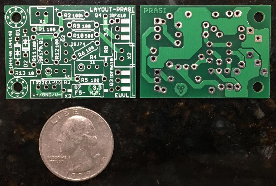
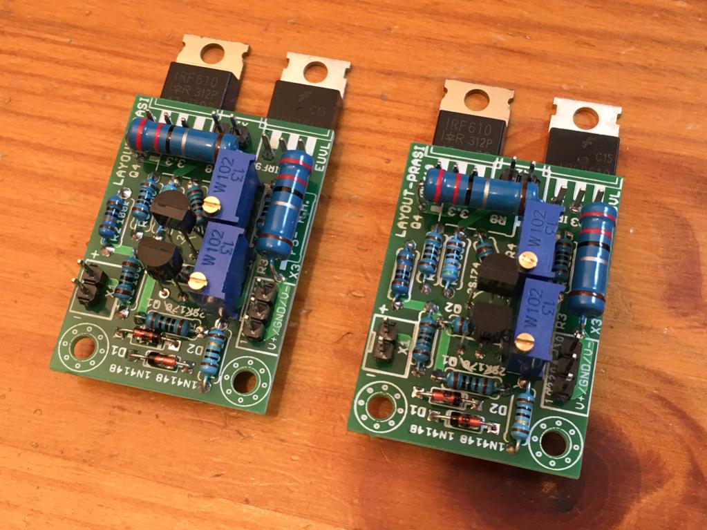
If you want an all FET headphone amp, try this one.
http://www.diyaudio.com/forums/pass-labs/271926-f5-headamp.html
Here is a layout that Prasi out together for it. Sounds fantastic - very quiet, super transparent, deep powerful bass. Just 4 FETs and running 100mA bias.
http://www.diyaudio.com/forums/pass-labs/271926-f5-headamp.html
Here is a layout that Prasi out together for it. Sounds fantastic - very quiet, super transparent, deep powerful bass. Just 4 FETs and running 100mA bias.
Last edited:
If you want an all FET headphone amp, try this one.
I want to finish my design 🙂
MOSFET SPICE model can in fact be quite pessimistic when it comes to predicting distortion. I think I ended up with two different IRF510 models at one point that gave markedly different results, and measured performance of the actual circuit turned out closer to the more optimistic one.
BTW, looking at that driven current source there, you may be in for a nasty surprise when simulating PSRR for your circuit. (EDIT: Turns out there is a PSRR problem, but it's actually rooted in the SRPP.) It is also a good idea to simulate distortion at 10 kHz.
BTW, looking at that driven current source there, you may be in for a nasty surprise when simulating PSRR for your circuit. (EDIT: Turns out there is a PSRR problem, but it's actually rooted in the SRPP.) It is also a good idea to simulate distortion at 10 kHz.
Last edited:
BTW, looking at that driven current source there, you may be in for a nasty surprise when simulating PSRR for your circuit. It is also a good idea to simulate distortion at 10 kHz.
I have simulated PSRR but I don't know what value is a good value.
Never mind, there was a sneaky AC component hiding in the signal source that was set to not display. As shown I'm getting about 40 dB of output PSRR across the band now, which is not spectacular but workable.
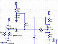
You get noticeably improved values (up to 67 dB below 1 kHz) if you give follower MOSFET M1 a source resistor with the value of R2, i.e. Aikido style.
Interestingly you can fine-tune this further by adding sort of a level shifter (see attachment - originally I just wanted to give the current source some better operating conditions). Playing with the R18/19 ratio, I can get this down to 77 dB and even lower, though this applies to ever lower frequencies and may require increasing C1. With 22k / 62-68k I end up at over 90 dB below 100 Hz (where high PSRR is arguably most needed) - that's op-amp territory, not bad at all. I am guessing you would play with a pot and a hummy unstabilized supply during prototyping stage to determine optimum values by ear. Unfortunately there's some correlation with DC operating points and (via Cgd) distortion performance. Going slightly higher than 15VDC for Vcc is to be considered either way.
Attachments
Never mind, there was a sneaky AC component hiding in the signal source that was set to not display. As shown I'm getting about 40 dB of output PSRR across the band now, which is not spectacular but workable.
You get noticeably improved values (up to 67 dB below 1 kHz) if you give follower MOSFET M1 a source resistor with the value of R2, i.e. Aikido style.
Hmm, it works. Have no clue how 😵
- Status
- Not open for further replies.
- Home
- Amplifiers
- Solid State
- Low voltage ZVN4306A vs IRF5xx/6xx is class A. Do SPICE lie to me?