Hi, I am trying to come up with a pretty simple Tube guitar preamp design ... I"m not good with tubes (not even good with solid state) but I came up with a design borrowing parts from other designs with some other ideas thrown in ....
I was wondering if you guys would take a quick look and tell me if if would work ....
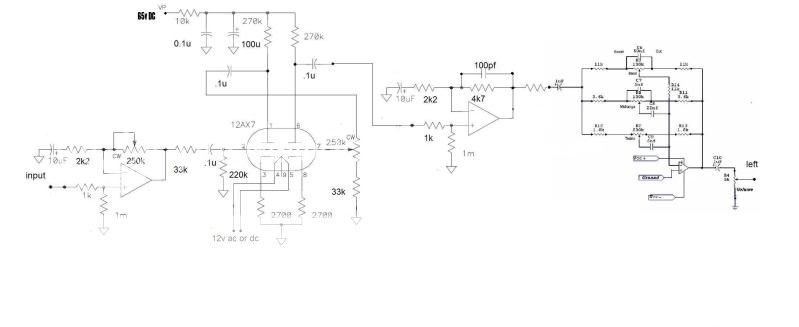
The first stage is a basic Non-inverting opamp which is intended to give a signal boost to help overdrive the Tube stage ....
The next stage is a 12ax7 Dual triode , it runs off of a 65v Plate voltage and 12 for the heaters ... it has a Pot between triodes to controll the signal going to the second triode ....
The next stage is just a simple Non-Inverting buffer with a bit of gain , it is to give a low inpedance signal to the next Inverting stage ...
The next stage is a Inverting Active 3 band tone controll , the purpose is well, to controll the tone ....
I know it is probably a pretty crappy design but will is work ??
Thanx a Lot guys/gals ....
Chris
I was wondering if you guys would take a quick look and tell me if if would work ....
The first stage is a basic Non-inverting opamp which is intended to give a signal boost to help overdrive the Tube stage ....
The next stage is a 12ax7 Dual triode , it runs off of a 65v Plate voltage and 12 for the heaters ... it has a Pot between triodes to controll the signal going to the second triode ....
The next stage is just a simple Non-Inverting buffer with a bit of gain , it is to give a low inpedance signal to the next Inverting stage ...
The next stage is a Inverting Active 3 band tone controll , the purpose is well, to controll the tone ....
I know it is probably a pretty crappy design but will is work ??
Thanx a Lot guys/gals ....
Chris
Try to experiment: move the 1'st opamp on place of the 2'nd one, with additional diodes in deedback (2 in series in one direction, and the 3'rd one in another direction in parallel with them). Such a way you may get more "tubey" overdrive.
As the result, you will have a tube preamp and a diode overdrive that gives nice logarythmic asymmetrical curves.
As the result, you will have a tube preamp and a diode overdrive that gives nice logarythmic asymmetrical curves.
Hi Wavebourn ... Luv yer work... Thanx for the Tips...
Most of the Guitar amps I have built have been solid state and I usually use Diodes as clippers (symetrical and asymetrical) so I was thinging about adding some clipping doides (Red LED"s are My Favorite) ...
But overall does the design look like it will work ?? at least put out sound ??
I was going to put it in front of a Bridged 150W TDA7293 Power amp , I built an amp recently which this design is based which sounds awesome , accept It was a PAIA Kit and a 15 band EQ and a single TDA7293 (they sound good in guitar amps as they actually sound good when clipped and bit) ...
Thanx a Lot...
You are welcome.
Try both ways and listen. I did not check tubes' working points, though... But I believe that your buffer will start saturating before tubes even approach their voltage limit.
Try both ways and listen. I did not check tubes' working points, though... But I believe that your buffer will start saturating before tubes even approach their voltage limit.
Minion
I would think that the AC signal on the plate of the second tube section would be 20+ volts P t P and that is too much for the op-amp to handle. Perhaps you don't need the second op-amp at all. By the way, can you point me to the values on the tone controls you have used? I cant quite view the drawing well enough.
I would think that the AC signal on the plate of the second tube section would be 20+ volts P t P and that is too much for the op-amp to handle. Perhaps you don't need the second op-amp at all. By the way, can you point me to the values on the tone controls you have used? I cant quite view the drawing well enough.
I don"t know what the output signal voltage from the second tube stage will be but the design I borrowed the Tube stage from has an opamp buffer after the tube stage so I think it should work ...
As for the tone controll section here is a bigger picture ...
Cheers
PS: here is the schematic I coppied the tube stage from with some minor modifications....
http://www.paia.com/prodimages/siabsch.pdf
As for the tone controll section here is a bigger picture ...
Cheers
PS: here is the schematic I coppied the tube stage from with some minor modifications....
http://www.paia.com/prodimages/siabsch.pdf
Minion said:I don"t know what the output signal voltage from the second tube stage will be but the design I borrowed the Tube stage from has an opamp buffer after the tube stage so I think it should work
You should be OK. The cathode resistors on the tube are unbypassed so the gain won't be so high.
Hi, Thanx , Would I get more gain if I put a capacitor in paralell with the cathode resistor ?? What Value for how much gain ?? Just out of curiosity ...
Cheers
Cheers
Minion said:Hi, Thanx , Would I get more gain if I put a capacitor in paralell with the cathode resistor ?? What Value for how much gain ?? Just out of curiosity
Well, if you put one there you'll probably overload one of the opamp stages as firechief suggested. You can put a 20-25uF there if you want to try. If you do your gain will be close to 100 for that triode.
While it is not completely low voltage the Hughes and Kettner Tubeman schematic might be worth looking at for some ideas.
It was discussed on this thread (with links to schematics).
http://www.diyaudio.com/forums/showthread.php?threadid=123124
Cheers,
Ian
It was discussed on this thread (with links to schematics).
http://www.diyaudio.com/forums/showthread.php?threadid=123124
Cheers,
Ian
Zobsky used a 12AX7 in that manner and had some problems
with his wire layout and oscillation. (-100) * (-100) = (+10000).
Too much non-inverting gain for any part of it to leak back into
the input, even by accident. And accidents happen...
We ended up paralleling both halves of his 12AX7, such that
the wire mess was coupling back only negative polarization.
You could still get your full 10000 voltage gain with a cascode
of triodes and have all the advantage of an inverting output.
But would need a taller working voltage for the plate.
Or maybe unity invert yet again, with an opamp inbetween
the triodes.... That might get you there.
Or pay very close attention how you shield and route those
wires wherever gain is so high.
Hi kenpeter,
do you mean to say that if the input wires (actually, I think shielded cable would be appropriate) of the first stage are too close to the output wires (again cables) of the second stage, you'll induce oscillation?
I'm asking because I have essentially the same design in one of my amplifiers and I used to have this very high-pitch wistle-like sound when the gain was maxed out. I managed to tame it with a 51 pF cap from the plate of my second stage to the B+ line. Inother words I paralleled the Plate resistor with a 51pF cap. I noticed that it did suck away a little bit of high end, but not enough for it to be "dull".
In any case, thank you. I can't believe how much I learn every time I read stuff on diyaudio!
- Status
- Not open for further replies.
- Home
- Live Sound
- Instruments and Amps
- Low Voltage Tube Solidstate Guitar preamp design ...