I need to design a +70V power supply for use with a low voltage tube preamp. I have 2 25V-0-25V center tapped transformers, and I would like to know if it would be possible to obtain 70 volts with these transformers.
I also need 6.3V @ 350mA for the heater supply (ECC88 tubes). If anyone has any help for such a supply then it would be greatly appreciated.
I am new to amplifier design, and I am having a lot of trouble with the power supply aspect of my design. Thanks ahead of time.
I also need 6.3V @ 350mA for the heater supply (ECC88 tubes). If anyone has any help for such a supply then it would be greatly appreciated.
I am new to amplifier design, and I am having a lot of trouble with the power supply aspect of my design. Thanks ahead of time.
http://www.kronjaeger.com/hv/hv/src/mul/
A PCB mounted transformer in this range should be pretty cheap..$2 -$3 Combine with LM317 and you are done.
A PCB mounted transformer in this range should be pretty cheap..$2 -$3 Combine with LM317 and you are done.
Do you know any good sites to find such a pcb mount transformer? With 4700uF smoothing caps and a full wave bridge rectifier, I can get an output voltage of +/-35V (no load). Is there any way to obtain 70V from this transformer?
Also, are there any voltage regulators that can be used for 35V and above? I haven't found any on the internet, but some regualtors specify a maximum differential voltage of 35V. Could something like this be used for greater than 35V? Thanks ahead of time for the help.
Also, are there any voltage regulators that can be used for 35V and above? I haven't found any on the internet, but some regualtors specify a maximum differential voltage of 35V. Could something like this be used for greater than 35V? Thanks ahead of time for the help.
mwl6m said:I can get an output voltage of +/-35V (no load). Is there any way to obtain 70V from this transformer?
Actually you do have 70volts (no load), just "ignore" the center tap, and place your voltage tester at the 2 other terminals for a reading.
best regards
Ebbe
So I would still use the bridge rectifier and use the negative rail as the ground reference voltage? This does give me an output of 70V, but I want to be sure to use the negative rail as the reference. Thanks.
I tried to supply the heater from a lab 6V power supply, but it did not draw very much current. Should the tube glow with only this voltage applied, or does the B+ voltage need to be connected in order for the tube to work? Thanks.
Here is a schematic of my heater setup. It is 6.3V paralled to pin 4 and 5 of a 9-pin tube socket. Would I connect the reference to ground or some other point? I've heard that 20-40V is a better reference with less hum. Any help would be appreciated, as this is one of my last steps to completing my tube preamp. Thanks.
Attachments
Just a bridge across the entire secondary (ignoring the center tap) will get you 70v, but without regulation. Adding half of the other transformer will get you 106v, which can then be regulated to 70v. (You can connect two secondary halves in parallel and use the ends to ensure load balancing.) At those voltages, it's easiest to use discrete components although there are regulator chips that can work with those voltages.
For the 6.3v supply, you can use a LM317 with the correct resistors or a 7805 with two 1N4148 diodes in the ground path.
BTW, I think tubes must be warmed up before applying plate voltage and plate voltage removed before filament voltage to ensure optimum tube life. There is a heat pump out there that uses a special oscillator tube to generate very high frequency AC (at about 900MHz) to defrost the coils with. It worked by forming a very lossy capacitor between the coil fins and the feeder wire with the frost as a dielectric. The frost first melts into water, which is even lossier so it heats up very quickly into steam. The steam then builds up pressure and blows the remaining frost and water out of the coil. In order for it to work effectively, the power must be very high for a short time, so very large capacitors were charged from a small transformer and discharged very quickly. Initially, the plate was connected directly to the capacitors and discharge started by applying filament voltage. It saved the cost of a high voltage switching device, but they experienced lots of early tube failures in prototype units. They realized that the cathode heats up unevenly during warmup so the hot spots took most of the load, causing them to wear out faster, thereby making them warm up faster next time, etc. until the tube burned out completely. Now, they use a high voltage SCR that is activated about 20 seconds after turning on the filament supply.
Would I still connect the center tap to the power star ground, or would I just ignore the center tap altogether? Also how would I connect up the heater so it is referenced to 20-40V instead of ground? Thanks.
Ignore the center tap. Also since the 50vrms you have will smooth out to about 70vdc with a bridge rectifier and caps, you may not need regulation. Most tube amps don't use any, but there are a few that do. Depending on your power transformer rating, you may be able to get 6.3v at 350ma, or you may not. A cheap radio shack transformer is also an option for that.
good luck
good luck
I am building a tube buffered gainclone. I am running +/-35V for the gainclone. Could I use an LM317T regulator to get the 6.3V@350mA I need for the tube heaters, or would this cause problems? Thanks ahead of time for the help.
If your transformer is capable of 350mA+tube current on half of the 25-0-25 secondary, then it is technically possible. However, using a regular voltage regulator like the LM317T will dissipate (35-6.3)*0.35 = 10 watts of power in that IC. Make sure you have a good sized heat sink on it. The dinky clip-on ones usually found will not do.
National also makes the "Simple Switcher" series voltage regulator that is much more efficient, but needs an inductor and will make switching noise, though I'm not sure how much of an affect it will have because I've never tried it in that scenario. (depends on switching frequency and ripple amplitude)
National also makes the "Simple Switcher" series voltage regulator that is much more efficient, but needs an inductor and will make switching noise, though I'm not sure how much of an affect it will have because I've never tried it in that scenario. (depends on switching frequency and ripple amplitude)
If I am using two seperate transformers, can I run both mains from the same wall outlet? or should I use seperate wall outlets for both transformers? l was thinking about running the heaters from my chip amp positive supply, and then the other transformer for my tubes. This would allow me to turn the chipamp on while also turning on the tube heaters, and that way I can wait to turn the tube power supply on to save its life. If this is feasible, is there any way to have an led that will light up once the heaters are ready, or some kind of timer that I set depending on how long I see that it takes the heaters to heat up? Any suggestions would be great. Thanks?
I also have this transformer from Radioshack http://www.radioshack.com/product/i...productId=2103732&support=support&tab=summary
It is a center-tapped transformer with dual 6V secondaries @ 450mA. Could I use this transformer for my tube heaters (6.3V@350mA). This might save the trouble of pulling this off of the chipamp positive supply. Would I have to use another wall outlet to hook up the transformer? Does anyone have any suggestions on which idea would work best (radioshack 12V transformer or using LM317 off of positive supply for gainclone)? Thanks again.
It is a center-tapped transformer with dual 6V secondaries @ 450mA. Could I use this transformer for my tube heaters (6.3V@350mA). This might save the trouble of pulling this off of the chipamp positive supply. Would I have to use another wall outlet to hook up the transformer? Does anyone have any suggestions on which idea would work best (radioshack 12V transformer or using LM317 off of positive supply for gainclone)? Thanks again.
Here is the actual link if you need it. Pretty standard description though.
http://www.radioshack.com/product/i...productId=2103732&support=support&tab=summary
http://www.radioshack.com/product/i...productId=2103732&support=support&tab=summary
If I am using two seperate transformers, can I run both mains from the same wall outlet?
Idealy, as it provides a central equal earth...
l was thinking about running the heaters from my chip amp positive supply, and then the other transformer for my tubes.
So what happens when your amp is delivering current... and the rail drops... will have not good effect on 6.3V...
I Would say 2 PCB mount transformers will do nicely...
the larger voltage one for your HV rail... I have a 2 x 12V one provideing + &- 70VDC at 15mA, think it iswas about 20VA (unfortunately it is sprayed black now, because I mounted it through the case...)
A smaller pcb mount transformer like a 7.2V 3VA can be used for the heater, just parallel the secondaries to ensure you have enough juice on tap. And it will have enough headroom once rectified, to regulate to 6.3V. These are realy cheap... and available, from, mouser, digikey, RS etc.
I saw the 450mA transformer you have, and yes, you can use that with the secondaries paralleled.
Another option is to include the regulation circuitry with your design, and use a 6 to 12 VAC wallwart (500 to 1000mA), for your heater.
I have been working with wiring up the tube's heater. I have a lab power supply that I have been using to try and test the tube, but when I apply the 6.3V, there is no current being drawn by the heaters. I have the heaters hooked up in parallel and referenced to ground, but it does not seem to want to work. Do I need some kind of resistor divider network to get the current I need, or am I just missing something obvious? Does the tube glow when the heater voltage is applied, or only after the B+ voltage is applied? Any help would be greatly appreciated. Thanks for the help.
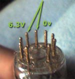
Why is the ground reference being connected to one of the tube pins? Shouldn't the ground reference be connected to the channel ground? That could be a reason why it is not working. It seems like something very simple that I should be able to fix. Thanks for the help.
woooooah.. getting ahead of ourselves...
This 0v is not related to your signal ground... it does not even have to be 0V... in all cases... this is purely seen in terms of a dc voltage supply for the heater... being 0v for this low voltage circuit, it is fine... to connect it to your groundstar.
now check those 2 things I said... will take only a few seconds...
- Status
- Not open for further replies.
- Home
- Amplifiers
- Power Supplies
- Low Voltage (+70V) Power Supply Design