Andrew,
f=50 Hz
phi=45 deg ( phase angle)
Z=25 ohms
__________________
Imagine a right angle triangle with real part being R
and imaginary part being Xl. Resultant vector Z
is a sum of these two. Angle between Xl and R is 90deg.
Because of phase angle being 45 deg, we know the imaginary
part is inductive, not capacitive.
sin phi= Xl/Z ; Xl=sin phi *Z
Xl=0,707*25= 17,67 ohms
Xl=2*pi*f*L;
L=Xl/(2*pi*f);
L=0,0562 H=56,2 mH
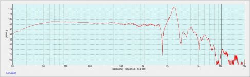
In post#22, near field measurements look very good, too good.
Zooming the impedance could reveal some minor issues, but overall it looks very nice up to 2kHz with no tendencies of major non linearities/resonances in impedance or phase. This correspond well to the near-field measurements although the near-field almost looked too good to be true 🙂
A great driver, a big solid box, no room interaction, and 1/6th octave smoothing = too good to be true. 😀 I should have done less smoothing, but Omnimic defaults to 1/6oct and I don't always remember to increase resolution before measurement. I am new to using it, but I believe that smoothing can't be changed after measurement.
Multiple people have told me that the sealed construction will be OK, and multiple people here have said go ported. Since I have the sealed already done, I will experiment with it until all my hair is pulled out. Besides too cold to cut new wood outside anyway. 😛
Moving the woofers halfway toward the front wall made an improvement yesterday, so today I moved them right up against the wall, cab sideways to get the woofer as close as possible to minimize bounce delay. Mains are on stands 4 feet closer to listener, electronic delay added, crossover reduced to 80. Bass sounds better, I think the problem is much lessened, but I have to work on integration with mains to know for sure. I am missing the dynamics I had with higher W/M crossover. But it's good result.
I will also try reducing the Vb to achieve Bessel alignment at Qtc .577.
Unfortunately I don't know your measurement system, but changing FR smoothing after the measurement has been taken should be possible... check also if post gating the measurements is possible - it can come in handy later on.
Try to forget about the Q for a moment. Is is IMO an uninteresting single parameter to discuss without knowing the response of the speakers in that specific room performs at that specific speaker-and listening position. Also, Q have greater impact in passive systems than in active DSP systems, where in DSP systems non-optimal speaker Q can be corrected to achieve the desired result. And for the record - Driver Q says absolutely nothing about driver quality, although many cheap driver's have high Q due to money savings on the magnet system. There are loads of stuff going on in a driver other than Q that is of importance to sound quality.
As you have seen already - the performance strongly varies with speaker- listening position.
To put it into context, each hump (tiny or large) in the frequency response considered to be minimum phase can be presented with its separate frequency, gain and Q and each have impact on (f...up) the impulse response by altering frequency specific sound pressure level and phase response. The good news is that any part of the frequency response that is minimum phase can be EQ-ed to achieve perfect impulse response. However not all irregularities measured are minimum phase, such as room modes. Consequently the only remedy to fight room modes is speaker/listening positioning to minimize the effect and acoustic treatment for those who are allowed to do so.
I can only encourage you to keep finding the speaker/listening position that contributes to the most even measurement result, meaning as few sharp spikes and notches as possible in the intended pass band for the bass speaker. Measure, move and measure. When you have find your best starting point, share the measurements for discussing the next step.
I am not surprised that you have found a more linear response close to the front wall. You will have fewer cancellations at this position as you have eliminated one reflective wall. Don't bother if you get too high gain in the bass, that can easily be attenuated by EQ-ing.
For your info, my woofers are placed at front wall and crossed over at 130Hz to integrate with a midbass horn. It works flawlessly with regards to bass response and integration. As long as your FR response is fine above 80Hz I would not hesitate to increase crossover frequency to gain more punchy bass and to put less strain on the midrange driver.
Regarding the cabinet you have, I run a simple simulation on it and found that you can convert it to a vented box tuned low. I would not bother to build a new cabinet for the purpose. But first, I will recommend you to keep the investigation going with the sealed enclosure as is.
Last edited:
Great advice, and just as I was thinking. I'll work on the positioning and incorporate the measuring. Thanks Tytte71
Rich
Rich
Hi Lojz,
thanks for taking the time to confirm my numbers (except capacitance) and to show more fully the method (90° phasors) that I omitted.
But, are you sure about the inductive load at 50Hz?
As frequency increases, a falling impedance indicates capacitance and a rising impedance indicates inductance.
This would indicate that below ~39Hz the load is inductive.
and above ~180Hz is also inductive. (except around the wiggle at >2kHz)
But the range from 41Hz to 140Hz is capacitive. Or, am I wrong?
You are right about inductive, capacitive and then again inductive
region which can be seen in post #56.
My calculation was based on the last paragraph of your post #60,
where you stated phase angle was 45 deg, f=50 Hz, Z=25 ohms which
are not the values from impedance measurement of post #56.
If the phase angle were -45 deg, your calculation of Xc=17,7 ohms
fora 180 uF capacitor at 50Hz would have been correct.
Obviously, whenever phase angle is negative, capacitive component
is there.
My post was about the impedance/phase vs frequency plot.You are right about inductive, capacitive and then again inductive
region which can be seen in post #56.
My calculation was based on the last paragraph of your post #60,
where you stated phase angle was 45 deg, f=50 Hz, Z=25 ohms which
are not the values from impedance measurement of post #56.
If the phase angle were -45 deg, your calculation of Xc=17,7 ohms
fora 180 uF capacitor at 50Hz would have been correct.
Obviously, whenever phase angle is negative, capacitive component
is there.
My values were extracted from that plot.
"180 uF capacitor at 50Hz would have been correct" should say "is" correct.
I don't know about you, but I see Z=14 ohms, at 50 Hz,
phase angle about -56 deg. You were misreading the
values for frequency and phase angle. Intersection of vertical
50 Hz line and Impedance(Z) curve is the value of Z,
the same for the phase.
phase angle about -56 deg. You were misreading the
values for frequency and phase angle. Intersection of vertical
50 Hz line and Impedance(Z) curve is the value of Z,
the same for the phase.
Last edited:
I will look again.I don't know about you, but I see Z=14 ohms, at 50 Hz,
phase angle about -56 deg. You were misreading the
values for frequency and phase angle. Intersection of vertical
50 Hz line and Impedance(Z) curve is the value of Z,
the same for the phase.
Note that post57 is next to post56.
I am using that plot for the data I extracted.
Last edited:
As well as I can see
it shows what looks like 25ohms at 50Hz and shows what looks like 45° at 50Hz.
A better pic would help, or is it my eyes?
it shows what looks like 25ohms at 50Hz and shows what looks like 45° at 50Hz.
A better pic would help, or is it my eyes?
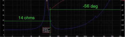
Impedance (blue) reads ~14 ohm @ 50Hz.
Edit: Lojzek's reply while I was writing is way more informative
Edit: Lojzek's reply while I was writing is way more informative
Last edited:
Don't neglect GROUP DELAY in this discussion
While frequency response of the woofer / box system, and how that system excites the room's modes, is PART of the picture that needs to be understood when trying to understand bass quality, another of the qualities separating a "wooly" sounding low end from a taut one is GROUP DELAY. There is something of a relationship between overall bass system Q and group delay, but Q doesn't tell the whole story.
Designing a ported system for absolutely lowest F6 almost always results in a system with high group delay in the lowest octaves. Settling on a slightly higher F6 in a ported system will lower group delay, so careful choices can give you a system with the punchy bass of near-optimal group delay and useful F6 extension over a sealed box.
A sealed box generally provides the lowest group delay for any given driver, but often the sacrifice of low frequency extension is so great that the woofer will sound thin. EQ can help here but there certainly are limits- more power at low frequencies will raise distortion and too much harmonic content in the bass will ruin the "tight" sound being sought. In addition, adding EQ can run up against excursion limits, available power and heat capacity of the driver.
Here's a link with more thoughts on this matter from Seigfried Linkwitz =>Frontiers
Last edited:
- Status
- Not open for further replies.
- Home
- Loudspeakers
- Multi-Way
- Low Qts in Low Qtc sealed box?