Hi,
I say build a 25L box and add 1L PET bottles with water until you're satisfied. With a Qtc higher than 0.7 you will have a hump around 70-90Hz I guess. It seems to me that you need it. I had these problems in a former room also, I made the box like this and then I had the luck with a peak near 45Hz that extended bass to around 35Hz. Doesn't cost much to try….
Personally, I want the kick drum to stand out and I can be without the lowest bass. Music must be fun to listen to, not analysed 😱)
Regards,
Peter
I can't think of any theoretical reason why this would be so.
If we consider the high Qtc equalized to low vs. a "genuinely" low Qtc, say for example we put the same woofer in a large box and a small box and equalized the small box case, what would be different? The compliance would be less with the small box combination and a greater percentage (of stiffness) would come from the cabinet air. Hard to say if that would effect linearity. The air in the box might be more linear than the woofer suspension, but I don't see a big impact from that. The Bl nonlinearity is the greater factor and it is the same for both
Thanks for your answer. Unfortunately, my post was not clear enough - I had on mind something different than your two examples.
From your first example (post 11) I understood that electronic equalization doesn't change much the bass character of the loudspeaker, irrespective of electronically derived Qtc (the same driver, with the same Qts). Your second example (post 39) deals with the same driver (the same Qts) in different box volumes (different Qtc). Again, equalizing to the same Qtc doesn't change the bass character much.
Based on my (very limited) experience with Linkwitz-transform circuit, I made exactly the same experiments from your two examples and came to the same conclusions. But with different drivers (different Qts) I noticed that drivers with low Qts when put in the low Qtc box (the "genuinely low Qtc", that is) sound "faster" and punchier than a high Qts driver in a high Qtc box equalized to the same low Qtc (the "fake low Qtc"). Am I correct? What is your opinion on this?
Last edited:
What is your opinion on this?
I will tell you what I have found out to be interesting.
Had a bass driver with a foam surround that was shot.
Originally it was a very soft surround. The sound of
the bass has always been on the soft side. Bought a
new pair of foam that were substantially harder to touch.
These have changed the TS parameters. Fs has risen 9 Hz,
Qts has risen also from 0,88(original) to 1,18. The Qtc was
held constant in both of the cases, about 0,9 without dcr of the
LP inductor calculated. The best part comes now. The overall
sound changed quite a lot and although the F3 was somewhat
lower with original surround, the bass became more punchy
with a new foam.
What does that tell us? There is more to it than just Qtc/Qts.
Check your measurements, Qtc must be higher than Qts. It is impossible to get Qtc=0.9 in a sealed box with driver with Qts=1.18. Also, to get Qtc=0.9 with driver with Qts=0.88 is next to impossible.These have changed the TS parameters. Fs has risen 9 Hz,
Qts has risen also from 0,88(original) to 1,18. The Qtc was
held constant in both of the cases, about 0,9
Sonce,
I'll make you a deal. If I prove here, that it is possible to adjust
the Qtc value lower than the Qts value of the same driver, you
will generously donate funds to this community and you will
get a star for it.
If I fail to do so, I'll admit I was wrong and sinbin myself from
this forum for a period of one month.
We would need an impartial person able to say who is right and
who isn't. Speaker Dave you trust, so maybe him.
Deal?
OB?High Q in OB is loose suspension and weak motor to allow cone overshoot that exaggerates bass extension and loudness to avoid the need for bass EQ making simple passive crossovers ideal. The price is loss of detail because neither the suspension nor the motor adequately controls the cone. Eminence Alpha 15 is the OB king, its Qts is 1.26! Low and loud with only a LP filter to your favorite fullrange at 300Hz. Low price makes a DIY dream. But poor detail doesn't blend with lowQ fullrange driver. It has a beautiful flat FR, but the hidden fact is it's all sine waves. 😱
I had this problem with an OB project, I used AE Dipole12 drivers (Qts .7.) They had too little detail. They blended poorly with my Feastrex. Another time I bought used servo OB subs but the servo sensors were broken so it was just high Q drivers in OB with no "electronic suspension." Same warm blurry sound.
That's really the problem I am having. Lack of detail, poor transient response. I have loose suspension just like OB speaker. I have high acoustic compliance similar to OB speaker. But I have a strong motor instead of a weak motor. Why is the strong motor causing worse transient response? Or maybe it's the high compliance not the strong motor that's the problem.
Madisound says my driver in sealed box should be only 19 liters, that's Qtc .88! Would the stiffer air spring make better transient response? A reflex port resists the cone motion too.
Do you mean a small baffle where the back wave is allowed to interfere with the front wave and thus ruin the loading on the driver?
OB?
Do you mean a small baffle where the back wave is allowed to interfere with the front wave and thus ruin the loading on the driver?
Yes, aka Open Baffle.
Sonce,
I'll make you a deal. If I prove here, that it is possible to adjust
the Qtc value lower than the Qts value of the same driver, you
will generously donate funds to this community and you will
get a star for it.
If I fail to do so, I'll admit I was wrong and sinbin myself from
this forum for a period of one month.
Deal?
Deal. But I don't want you to punish yourself with one month away from this forum, so stay here.
It is possible to lower driver's Qts with applying damping immediately behind the driver, so this little trick is out of deal.
Sonce,
you are not being fair with stating that I might be pulling
tricks on you. Go to your post #45 and read it again.
I was very clear about what I can prove and now you're
saying you agree to a deal but with a condition of yours!
Since it is obvious that you are getting cold feet, I conclude
I proved my point without executing the necessary measurements.
I can't recall seeing an advised range of Qts for a small baffle.
I hear ya. I figured it out the hard way. I don't think that there is an officially advised range of Q for OB drivers, like there is (EBP) for port and sealed, because low Q and Hi Q are both valuable to the OB wing of the hobby, so there are only opinions. Since active EQ/amp and low Q drivers all cost money and require more knowledge and effort than cheap hi Q drivers and plywood, the myth of HiQ in OB has become more popular, and driver manufacturers feed the demand and add credence.
As for expert opinions, Martin King has used high Q bass drivers in his own OB project, whereas Siegfried Linkwitz uses low Q bass drivers with EQ in his OB project Orion. Rythmik offers servo ob subs which are effectively a Linkwitz Transform for OB speakers. 🙂 They supposedly sound very clean tight, low and loud. But I've still not heard it myself, although I tried.
First three results about Q in OB (leaning toward high Q) in my search:
Open Baffle - Loudspeaker Design Part 16
Designing Loudspeakers - Open Baffle speakers - The Trials
http://www.diyaudio.com/forums/full-range/186571-qts-openbaffle-how-low-can-you-go.html
Tim, thanks for the PM.
Tytte71, I have moved the speakers around, makes a big difference in the presentation and bass quality. I do still hear the hollow boominess. Does it makes sense to explore ports next?
Tytte71, I have moved the speakers around, makes a big difference in the presentation and bass quality. I do still hear the hollow boominess. Does it makes sense to explore ports next?
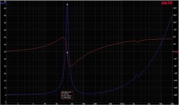
For that phase plot, note that where the phase becomes zero degrees as it crosses over the 0° horizontal, the speaker presents an exactly resistive load. The value of that non reactive load is read off the impedance plot at the same frequency.
i.e at ~40Hz it is ~67r (not ohms) and at ~170Hz it is ~6r (again not ohms).
Where the phase is rising (increasing above the 0°, or changing from -ve° to +ve°) as frequency increases, the speaker presents an inductive load, i.e. it behaves as a series combination of a resistor and an inductor.
And the corollary is: where the phase is falling as frequency increases, the speaker presents a capacitive load.
*********
Could someone comment on the accuracy of this next paragraph? I am unsure what is happening when the phase has turned to horizontal, i.e. no longer falling, just as it reaches 45°.
*********
If the phase reaches 45° at any frequency, then at that frequency the speaker presents a reactive load that has two components that are equal, i.e. Xc or Xl = R
Using the 50Hz value we see phase is 45° and impedance is ~25ohms.
The two components will be 25/sqrt(2), = ~17.7ohms. i.e. the speaker presents a complex impedance consisting of a 17r7 resistor in series with a capacitor of ~180uF (Xc=17.7ohms @ 50Hz).
Last edited:
For the understanding on what's going on and optimize the bass (impulse) response you don't have to convert to ported enclosure. I recommend to find the optimal speaker/listening position and gentle EQ the response until a satisfied result is achieved (reponse is linear / booming is eliminated). Please share measurements and EQ settings as you progress and it would be a little easier to assist.Tim, thanks for the PM.
Tytte71, I have moved the speakers around, makes a big difference in the presentation and bass quality. I do still hear the hollow boominess. Does it makes sense to explore ports next?
However, and as stated previously, you will gain capacity (factor of >2) and reduce nonlinear distortion ad modest listening levels by converting to ported enclosure. Group delay might be a little higher with ported enclosure in the sub octaves, but you need IMO to try and optimize before you conclude on its audibility.
Zooming the impedance could reveal some minor issues, but overall it looks very nice up to 2kHz with no tendencies of major non linearities/resonances in impedance or phase. This correspond well to the near-field measurements although the near-field almost looked too good to be true 🙂Impedance / Phase in closed box. No blips in passband. Fc = 38Hz
I see my mistake, The post has been altered slightly to correct that error:
For that phase plot, note that where the phase becomes zero degrees as it crosses over the 0° horizontal, the speaker presents an exactly resistive load. The value of that non reactive load is read off the impedance plot at the same frequency.
i.e at ~40Hz it is ~67r (not ohms) and at ~170Hz it is ~6r (again not ohms).
Where the **impedance** is rising as frequency increases, the speaker presents an inductive load, i.e. it behaves as a series combination of a resistor and an inductor.
And the corollary is:
where the phase is falling as frequency increases, the speaker presents a capacitive load.
*********
Could someone comment on the accuracy of this next paragraph? I am unsure what is happening when the phase has turned to horizontal, i.e. no longer falling, just as it reaches 45°. ** it's not the phase turning to parallel that is the condition !!!!
It's impedance becoming parallel to the horizontal axis that is the condition we should be looking for.
*********
If the phase reaches 45° at any frequency, then at that frequency the speaker presents a reactive load that has two components that are equal, i.e. Xc or Xl = R
Using the 50Hz value we see phase is 45° and impedance is ~25ohms.
The two components will be 25/sqrt(2), = ~17.7ohms. i.e. the speaker presents a complex impedance consisting of a 17r7 resistor in series with a capacitor of ~180uF (Xc=17.7ohms @ 50Hz).
- Status
- Not open for further replies.
- Home
- Loudspeakers
- Multi-Way
- Low Qts in Low Qtc sealed box?