Supertex low power mosfet's - complementary pairs
Hi mlloyd1,
Their gate drive dynamic characteristics are really quite close.
It doesn't take much difference in associated bias circuitry, especially when operated in class A mode to produce transfer characteristics as exact complements.
Get some and try them out, or even just simulate them in a few typical (or perhaps not so typical, whatever you are into) audio circuits to convince yourself.
The thing I like most about Supertex is they are so willing to work with you. They will produce custom semiconductors or mount their die in just about any package you need. They have been very generous with samples too.
They have produced a lot of really great semiconductors over the years.
Best Regards,
Rich
Supertex low power mosfet's - complementary pairs
Hi Everyone,
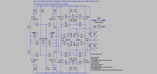
Here is a little sample of what I meant in my previous post about bias.
By the way, the Nirvana Line Driver (my design) I posted here, sounds really good.
And yes, the design adapts very well for much higher power output with the right outputs.
Enjoy.
Best Regards,
Rich
Hi Everyone,
Here is a little sample of what I meant in my previous post about bias.
By the way, the Nirvana Line Driver (my design) I posted here, sounds really good.
And yes, the design adapts very well for much higher power output with the right outputs.
Enjoy.
Best Regards,
Rich
Attachments
Supertex low power mosfet's - complementary pairs
Hi Andrew,
A very good question and thank you for your interest.
I have made the circuit with all kinds of variations for better than 10 years.
I would not use either E24 or E96 series.
Resistor tolerance is quite critical in the circuit.
Use E192 series with a tolerance of at least 0.1% or better if you can.
I make up the 596 values with a 189 and a 407.
Run the LTspice model I posted to determine the minimum power ratings you will have to use.
Best Regards,
Rich
Supertex low power mosfet's - complementary pairs
A few more things about the circuit.
For variable gain I normally series 412 ohm with a 100K pot in place of the "Input Padding". With 100k padding it will swing an honest 22 volts into a 600 ohm load.
You can also directly (without any other changes) parallel more outputs for greater current capacity.
Best Regards,
Rich
That's a surprise, I am glad I asked.
Is absolute 0.1% tolerance critical, or can relative, or matching, to 0.1% variation meet the performance standard?
Is absolute 0.1% tolerance critical, or can relative, or matching, to 0.1% variation meet the performance standard?
Resistor tolerance is quite critical in the circuit.
Could you please elaborate a bit why such a tolerance is needed?
Supertex low power mosfet's - complementary pairs
The less the differences between mirror segments the lower the distortion.
Rich
The less the differences between mirror segments the lower the distortion.
Rich
Ok, but how would such a low difference in resistor values (590R vs 596R) correct serious difference in N-mos vs P-mos gm and I-V characteristics?
Not Relevant!
Please do not confuse the posts.
The original post by Bensen was a good question about - "Low power mosfet's - complementary pairs".
His post caught my interest because it has been getting increasingly difficult to find readily available complementary pairs.
In my line of work, I have had to get very creative. This being DIYAUDIO, complex circuits are beyond the scope of most members to be able to make.
I posted about a pair of Supertex DMOS TN2640 & TP2640, that although their published gm and I-V characteristics being apparently quite different, can be utilized in ways to produce outstanding results.
The intent entirely was to inspire others to look beyond just the obvious published characteristics of devices. In other words, what can be done with it?
I then posted a workhorse of a design utilizing those Supertex DMOS I mentioned, to provide an actual example of an amplifier designed specifically for driving long cable runs that even though it doesn't utilize any global feedback, it produces quite outstanding results.
Again the intent is to inspire others by showing what can be
made with devices that are apparently quite different. I purposely chose a simple design that only utilizes those two Supertex DMOS devices throughout it.
Somehow the direction of this discussion has gone off to a question "how would such a low difference in resistor values (590R vs 596R) correct serious difference in N-mos vs P-mos gm and I-V characteristics?"
The answer is that the difference in resistor values (590R vs 596R) has nothing to do with correcting any "serious difference in N-mos vs P-mos gm and I-V characteristics", nor did I never state anything of the sort in the first place.
The difference in resistor values (590R vs 596R) corrects a small (measured) offset of the output signal found with typical produced devices, that is not at all depicted with any simulator I have ever used.
The Nirvana line driver was designed specifically for large scale PA system use. I only shared my design to inspire others to look beyound published characteristics and perhaps let those that may be interested in this topology to study it and furthermore apply it to other amplifier applications if they so chose.
Sincerely,
Rich Borkowski
- Status
- Not open for further replies.
- Home
- Amplifiers
- Solid State
- Low power mosfet's - complementary pairs