Hi Guys
You are seeing miserable performance from the JLH because that's what it offers. Does nobody read Electronics World ( used to be Wireless World) ? It was amplyy demonstrated that there is no idle condition where the signal smoothly passes from one output device to the other. Why bother with it?
The only attraction either of the circuits you simulated offer, is the nominal no bias control. The diamond has to be operated pretty much class-A to drive a speaker this way. Its performance depends entirely on the constant current sources that actually turn the output devices 'on'. The input stage only turns them 'off'. The diamond is okay for line level buffering, but...
You said you want to drive speakers.. A diamond is not the best choice.
My recommendation above is something that is pretty conventional. Conventional is common because it works. You can choose a more difficult path and/or one that will result in worse performance. Anything you build that functions will sound good to you for a while....
Have fun
Kevin O'Connor
jerluwoo thanks for that, so the idea waasn't totally crazy. The figures were quite respectable too (-60dB for 1V and -100dB for 100mV open loop)
Kevin, I appreciate what you are saying about something conventional, but I'm just experimenting at the minute. The diamond and the class AB can both use the same output stage (complimentary emitter followers with current balancing), so I might build both front ends and compare.
I think that's the answer then, diamond buffer and class AB (sorry jerluwoo). Will try to get parts sorted this week and have a go.
Thanks everyone for the suggestions, and if anyone spots a mistake in my sims that means it's -9dB for the distortion and not -90dB, let me know🙂
Brian
Hi Guys
The article I referred to above is "Few Compliments for Non-complements" by Doug Self, Sept. 1995 Electronics World.
Have fun
Kevin O'Connor
The article I referred to above is "Few Compliments for Non-complements" by Doug Self, Sept. 1995 Electronics World.
Have fun
Kevin O'Connor
Ah that one. To be fair, some of the criticisms in that article aren't applicable here as this is a different architecture again (my middle transistor isn't the VAS...)
Brian
Brian
Hi Guys
You can call any of the stages anything you wish to, but if the output structure is the JLH type, it will have all of its flaws. Some people like those flaws, maybe that includes you? I liked them when it was the first amp I built and then I built better things....
Have fun
Kevin O'Connor
You can call any of the stages anything you wish to, but if the output structure is the JLH type, it will have all of its flaws. Some people like those flaws, maybe that includes you? I liked them when it was the first amp I built and then I built better things....
Have fun
Kevin O'Connor
if the output structure is the JLH type, it will have all of its flaws
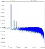
Hi Kevin, not sure what you are getting at here. The article (I have a vague memory of it, refreshed by Google), criticises the input stage, using the phase splitter to provide voltage gain and using FETs. I have suggested none of these. It also criticises the feedback factor at high freuencies; I have no gain (it being provided by the pre-amp and using the pre-amp's feedback), and the -3dB bandwidth is in excess of 100Mhz, so I don't see that being a problem. The only remaining criticism with relevance that I can find/remember is the output stage non-linearity, but the sims I did (-60dB for 1V and -100dB for 100mV open loop) aren't too shoddy, especially when you conside that it is all low order harmonics. FFT at 1V attached.
Is there something I've missed here?
This is just out of interest, I've decided not to build this version anyway...
Best Regards,
Brian

I think of it as a JLH with the middle transistor upside-down, and imagine (no sim software or test equipment at the moment), that the top transistor works as an emitter follower with an active load formed by the bottom transistor (one of the definitions of the JLH).
Is this likely to work?
Yup, your idea should work pretty well. It's actually the upper half of a diamond buffer, combined with a CFP lower half, so it's sort of quasi-complementary push-pull. If the biasing is in the right range, it simulates very well and it should also work and sound good - the dominant distortion component is H2.
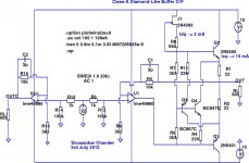
For small-signal applications, where the current gain is not required to be as high as your topology (or a standard diamond buffer), I have a different circuit (shown below) that simulates with lower THD20 numbers for similar output-stage bias currents (in the case shown below, about 10 mA).
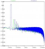
It's more elaborate, with an additional NPN and more resistors, but with better bias stability. I've called it the Diamond-like Buffer or Diamond Cascode. When used as a current-booster for a conventional opamp, it completely transforms the sonics - as shown below (the left half is the control for comparison without current boosting, and the right half uses the diamond cascode for current boosting), it's possible to get up to 30 dB reduction in H3 and higher odd harmonics, and with H2 as the dominant THD20 distortion component (much like your topology), with a standard high-performance opamp as a 4x voltage stage.
(A full-fledged diamond buffer could perform even better, as you noticed in simulation, but it needs multiple current sources, careful bias optimization and BJT matching. The diamond cascode does ok even with moderately mismatched complements).
Attachments
Yup, your idea should work pretty well. It's actually the upper half of a diamond buffer, combined with a CFP lower half, so it's sort of quasi-complementary push-pull. If the biasing is in the right range, it simulates very well and it should also work and sound good - the dominant distortion component is H2.
It works even better with a reactive bridge, aka Quad-style current dumping, as shown. H2 dominates as before, and the odd harmonics get clobbered pretty good.
In practice, the L1 (10 uH) has to be air-core for best results, so the size may prove to be a limiting factor.
Attachments

Last edited:
Thanks linuxguru, I like both of those, but I have stated building the diamond buffer. I'm hoping matching won't be too much of a problem, but if it is, I can always change to your first suggestion, as it still uses complimentary transistors. I decided class A with no heatsink would be an interesting challenge, so I have used 10 NPN and 10 PNP small signal transistors to make the output stage, and the thought of replacing 10 transistors PNP for NPN has ruled out your second suggestion for this project. Since I'm building four of these (active crossover), I'm tempted to make two of your first suggestion and try them out. I might prefer that way for the tweeters or the bass/mids.
I need to get one working first and my spare time has disappeared since I started soldering - why does that always happen?
Brian
I need to get one working first and my spare time has disappeared since I started soldering - why does that always happen?
Brian

Hi Guys
That design looks unstable. I suppose human nature being what it is predicts such a result, going from the JLH to this (post-30). JLH sims okay in some regards but does not quite work as such in real life. Drive a speaker with it and hear the distortion. You'll either like it or not, or like it for a while and grow tired of it eventually.
Diamonds are not known for their linearity, rather their speed. The boring conventional option provided earlier outperforms the experimental circuits in the real world and is a lot simpler than what is now being discussed. Wasn't cost an issue at the start of this? Or did your dog win?
Have fun
Kevin O'Connor
Hi Guys
That design looks unstable. I suppose human nature being what it is predicts such a result, going from the JLH to this (post-30). JLH sims okay in some regards but does not quite work as such in real life. Drive a speaker with it and hear the distortion. You'll either like it or not, or like it for a while and grow tired of it eventually.
Diamonds are not known for their linearity, rather their speed. The boring conventional option provided earlier outperforms the experimental circuits in the real world and is a lot simpler than what is now being discussed.
The original posting was a topology that is only superficially similar to the original JLH (which has 3 NPNs including the phase-splitter/VAS). The ones in this thread are pure current-gain buffers, with no voltage gain at all, and all are extremely stable. They have very little in common with the original JLH 3-NPN gain stage.
The one is post #27 (Diamond Cascode) is already built and tested - it's running fine as a current-booster for an LM318 in a MyRef Rev C. I'll open a thread for this topology later.
The one in post #28 just adds the reactive bridge to the current booster of post #1, with all the pros and cons (already well known) of the quad current-dumping topology.
The one in post #30 is a conventional diamond buffer, and will again work fine, with a little bit of attention to matching.
Incidentally, diamond buffers can be built with both high-bandwidth and linearity. Check out the 'Discrete Opamp Open Design" thread for Scott Wurcer's SWOPA topology, which uses one such elaboration of the diamond-buffer as the output stage.
Sure, it's possible to build simpler current boosters - a single BJT emitter follower, or its complementary push-pull variant both fit the bill. Once you add components for biasing and stabilization, it's not quite as simple any more.
The one is post #27 (Diamond Cascode) is already built and tested - it's running fine as a current-booster for an LM318 in a MyRef Rev C. I'll open a thread for this topology later.
As promised, here's the link to the new thread about the Diamond Cascode:
http://www.diyaudio.com/forums/anal...-like-buffer-current-booster.html#post3582199
There seems to be no end of possibilities of adding current buffers to an opamp, and I bet that most perform well because of the high feedback of the opamp. I chose the diamond buffer because it gave the least distortion open loop, with all the harmonics below -85dB. My speakers are very efficient (98dB @ 1W), and totally unforgiving of poor amplifiers - most commercial offerings (class AB) don't sound good at all at low levels with these, so the diamond buffer seemed the obvious choice. Having said that, if I had linuxguru's designs before I started construction...
It is likely to be unstable, opamp is a two stage amplifier, and regularly designers need pay great deal of attention to squeeze performance with certain phase margin. Added stage is an extra amplifing stage, not a simple voltage buffer, thus will introduce extra delay to the feedback loop, push the phase margin below zero is likely. 3 stage amplifier is much more difficult to stabilize, better to avoid it if you can.
I don't know too much about this, but are you sure? The design is basically a (simplified) discrete LME49600 (and many others) which is also used inside an opamp feedback loop. It has a gain <1. The bandwidth of my buffer in >500Mhz and the opamp (TL071) has a unity gain bandwidth of 3Mhz, so I'm not convinced that any delay in the buffer will affect the opamp at all.
Updating to include these relevant threads:
http://www.diyaudio.com/forums/soli...llower-diamond-buffer-power-output-stage.html
http://www.diyaudio.com/forums/solid-state/194453-very-simple-class-b-amplifier.html
Mine is just a mixture of the two.
Construction has started, just got stuck on the power supply - too many other things miraculously appear at this stage in a project and take up all available free time. Anyway, will get there in the end - it's not a race.
Brian
Here is a variation that my be of interest to you as well,
http://www.diyaudio.com/forums/soft...ettings-inconsistent-results.html#post2942631
Also I just built a current boosted output stage using a couple of complementary small signal BJT's driving a BD911 and BD912 for an output stage.
It works great, I can draw up the schematic if you like.
It is a class AB type whith the bias set about 70ma's but is adjustable and I can also increase the bias as well for class A.
I have ran it as high as 1.2 amps or so (so far) which is the limit of my +/- 15V bench supply.
I also used a LME49860 and it works very well single ended as well.
On just 15V however its voltage swing is limited to what the opamp can do (12V p-p for 15V SE).
I haven't done a whole lot of testing with it yet but it does work great and produces a very clean signal into 8 ohms.
My next tests will be with a higher current supply (that I have yet to build) and more output devices.
Very simple and very low parts count !! 🙂
Cheers!!
jer 🙂
Last edited:
- Status
- Not open for further replies.
- Home
- Amplifiers
- Solid State
- Low power amp by adding current buffer to preamp