Just a quick question here. What if I wanted to make an active woofer, using a pretty standard LM3886 and a simple low-pass. Can't I just increase the size of the cap between the positive and negative input, so I make a low-pass filter like that? Say, between 0.05 and 0.005uF, depending on what I'm doing? And make it a good polyprop cap, while at it.
Not that cap, that one is used to reject RF hash. You are best off putting an active filter before the amp. You can use a passive filter, but their response is too droopy I feel.
The worst way would be to add a cap in parallel with the feedback resistor. In non-inverting mode you would still get treble bleedthrough as the lowest gain you can have is 1 and the roll-off is just 6dB/octave which is pretty poor. Also the chip is probably not stable at unity gain.
The worst way would be to add a cap in parallel with the feedback resistor. In non-inverting mode you would still get treble bleedthrough as the lowest gain you can have is 1 and the roll-off is just 6dB/octave which is pretty poor. Also the chip is probably not stable at unity gain.
If I put a filter before the amp, I'd make a good, active filter. But really - I couldn't think of any side-effect of increasing the inputs cap to the point where it'd attenuate enough to get down in the audio band. So I'm looking to find one, so I can focus on the active low-pass then 🙂
I wouldn't filter an LM3886 trough the feedback no. IIRC, it's far from unity-gain stable. Thanks for reminding me though, considering what I'm asking, I shouldn't be forgetting anything about it.
I wouldn't filter an LM3886 trough the feedback no. IIRC, it's far from unity-gain stable. Thanks for reminding me though, considering what I'm asking, I shouldn't be forgetting anything about it.
Last edited:
A chipamp is just a high powered opamp, so it can be configured as a 2nd order LP (or HP) filter (or even fudged into a 3rd order).
True to some degree only - chip amps are not unity gain stable without some fudging networks around them - the K value in your diagram is unity for a typical Sallen-Key configuration.
I use a 6dB network in front of the chipamp, and another in front of the preamp (if present/necessary). Works well enough - if you need steeper slopes, active filtering is the way to go.
High pass is significantly easier, I just use a small feedback capcitor (Ci) to provide additional 6dB rolloff, plus the 6dB in front.
The one time I messed with the series feedback path I had severe issues with howling feedback, so I didn't pursue that road (STK chip and speakers both survived the ordeal).
The cap between the inputs is also a feedback path, IINM. I'd be interested in the results of this increase, it does seem like a good place to provide rolloff but never tried it myself.
Well, I'll give it a shot and I'll see how it goes. It would be nice to measure freq. response with something though, so I can confirm how it works.
I'm talking about Cs in a configuration like this:
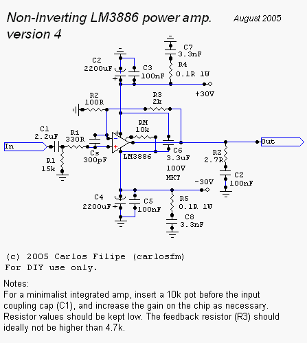
That's not the schematic I'm doing, but it'll do as an example. Just bump Cs to a suitable value for my woofer?
I'm talking about Cs in a configuration like this:
That's not the schematic I'm doing, but it'll do as an example. Just bump Cs to a suitable value for my woofer?
Last edited:
You would be better putting a cap from the non-inverting input to ground, in conjunction with the 330R it will form a traditional low-pass filter.
Well, that is a fair point, I wouldn't need a bigger cap for that.. Oh well 🙂
I'll either install whatever is easier to fit on the board I've got, or I'll place an active filter before it.
Thanks!
I'll either install whatever is easier to fit on the board I've got, or I'll place an active filter before it.
Thanks!
Just a quick question here. What if I wanted to make an active woofer, using a pretty standard LM3886 and a simple low-pass. Can't I just increase the size of the cap between the positive and negative input, so I make a low-pass filter like that? Say, between 0.05 and 0.005uF, depending on what I'm doing? And make it a good polyprop cap, while at it.
That would be a first order low pass filtrer, not much of a roll off, but yes.
Another almost free thing to do is to look at you negative feedback loop. Certainly there is a resister ther that controls the fraction of to output that is sent back. You can bypass that resister with a cap so that almost all of the high frequency signal is feed back. This has the effect if killing the gain at those high frequencies. Basically this turns you big chip amp into an active low pass filter. Side effect is that you can be pretty sure it will not ever have any high freq. oscillations, even with poor layout
Do the active filter, 6dB/octave is rubbish on a sub.
A single sub, probably not enuff, but with a pair, and the right system combo, 1st order might be just fine.
dave
Another almost free thing to do is to look at you negative feedback loop. Certainly there is a resister ther that controls the fraction of to output that is sent back. You can bypass that resister with a cap so that almost all of the high frequency signal is feed back. This has the effect if killing the gain at those high frequencies. Basically this turns you big chip amp into an active low pass filter.
No, it has the effect of turning your big chip amp into a high power oscillator.😱
Side effect is that you can be pretty sure it will not ever have any high freq. oscillations, even with poor layout
Ironically, quite the opposite. You can be totally sure you'll never have any stability, even with perfect layout.😀
<edit> It is possible, though rather difficult to use the chip amp itself in a low pass filter. I've tried it on the sim, but I don't trust the simulation enough to post up the schematic - simulators often don't show up instabilities in circuits without more complex analysis of the feedback.
Last edited:
between 0.05 and 0.005uF, depending on what I'm doing?
What crossover frequency does your woofer need? In conjunction with a 330 Ohm series resistor you get -3 dB at 9,65..96,5 kHz depending on what you're doing?
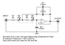
What crossover frequency does your woofer need? In conjunction with a 330 Ohm series resistor you get -3 dB at 9,65..96,5 kHz depending on what you're doing?
I'm working on figuring that out still. I've a mystery speaker to work with 🙂
Can you post the schema you are using?
I can't recall seeing a shunt cap on a gain clone.
A chipamp is just a high powered opamp, so it can be configured as a 2nd order LP (or HP) filter (or even fudged into a 3rd order).
An externally hosted image should be here but it was not working when we last tested it.
Body
dave
For a K of one - would a voltage on the output divider work? For instance, if the amplifier gain was 21, the use a 1k and 50 ohm divider to feed the c1 cap.

- Status
- Not open for further replies.
- Home
- Amplifiers
- Chip Amps
- Low-pass for Active woofer Gainclone