I need to build a better set of low pass filters for my test setup. I need to build a set of high power filters for my scope and distortion analyzer inputs that will allow me to test class-D amps up to 500 watts from 20-20khz.
What I have now is 12db oct at 20khz and that allows me to test up to 5khz at full power, if I go over 5khz at more than a few watts i burn them up which has happened more than a few times.
SO. Suggestions? maybe 24db at 100khz? with an 8/4 ohm resistive load?
Can I use standard speaker crossover calc's to do the math??
where Eva?
Zc
Last edited:
I will check it out. I am not using a software based test set up. and right my filters connect to the input of my scope and my dist an. but my filters are made up of a series resistor / inductor and a capacitor to ground and as you start getting above 5khz there is sufficient energy to burn up the low wattage resistor and inductors as you are getting into the tail of the 12db down points of the 20khz filter
Ok well it's great that AP makes that product but i am quite sure I can't afford ANYTHING with the AP name on it. I need to BUILD one!
Well, the AP filter is on the order of 800EUR and quite unlikely to be found used. I have one at work but it's still having the screws sealed so no way to peek inside...
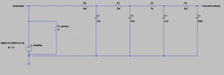
I am typically using passive RC filters in the range of 3rd...5th order. Similar to the 4th order filter in the attached picture.
Chose a 5W type for the 100 Ohms and 1 W for 330 Ohms, all the rest 1/4W resistors. Caps should be MKP types with 100V rating (lower quality will still work....).
Chose a 5W type for the 100 Ohms and 1 W for 330 Ohms, all the rest 1/4W resistors. Caps should be MKP types with 100V rating (lower quality will still work....).
Attachments
I need to get out to 20khz flat before roll off. part of my testing involves full power frequency response so i need to make sure the filter is not causing problems at 20khz
I would think with a well-known roll-off you could account for that easily in the measurements. Flat response (how flat, <0.1dB?) and sharp roll-off complicates filter design and construction quite a bit.
Of course, you can adjust the transferfunction according your taste.
The shown values were just anticipated from your first posting to fit -3db at 20kHz. Feel free to make the filter faster unless your analyzer gets irritated because the switching residuals are not suppressed sufficiently anymore.
Or simply measure the full power frequency response with a function generator and the scope directly, you do not need any filter for that at all.
I would think with a well-known roll-off you could account for that easily in the measurements. Flat response (how flat, <0.1dB?) and sharp roll-off complicates filter design and construction quite a bit.
Yeah within .1 to .2db accurate to 20khz. most of the switching frequencies seem to be 300-400khz or so so I figure if i have a 100khz low pass filter that should be good enough to keep the junk out of the analyzer yet give accurate results.
I have that AP filter at work, if something external you want measured?
Not volunteering to void warranty by opening the cover. Its brand new.
Not volunteering to void warranty by opening the cover. Its brand new.
I think a filter set like this would be beneficial to anyone working with Class-D amps. Im surprised there hasn't been a discussion as such before?
You want to build it from scratch, but are not willing to calculate or simulate anything on your own, even after circuit examples and software proposals have been given?
And at the same time you demand 0.1db at 20kHz, but high attentuation at 300kHz?
Sorry, servant choco feels ripped off.
And at the same time you demand 0.1db at 20kHz, but high attentuation at 300kHz?
Sorry, servant choco feels ripped off.
Well for 1 I don't know how to calculate such a filter and I have no way of simulating anything! I have never gotten into the whole software sim deal. too steep of a learning curve for the time i have. I will build and try your schematic. but I wasn't sure if that would do what I needed? I was looking for someone to explain HOW to do the calculations for a filter so I could do the math myself. Not necessarily do it for me!
With Choco's circuit the math is quite easy. It's based on sligthly loaded RC's, scaling impedance by 3x from stage to stage downstream, forming a N-th order cascaded RC lowapss. Therfore the final roll-off is (n*6dB)/oct and the response is (n*3)dB down at the pole frequency f=1/(2piRC), with n being the number of stages. EDIT: these are ballpark values only. In fact the loading of each stage will introduce a "fudge factor" if you only rely on that simple approximation.
Because of the scaling impedance you must not load the output down and the higher-Z sections of the filter are prone to stray pickup and crosstalk, making wiring not an easy task).
If you really want to go with more complex higher-order, even cascaded LRC-filters, the math and calculations reuired to do it analytically on paper will be most annoying I'd say.
With a simulater you'll beat that in a hour (again LTspice is the swiss army knife and IMHO easy to handle and well supported).
Googling pops up with LRC-filter tools as well, like this one :
RLC Low-Pass Filter Design Tool including all background information, and the whole site is worthwhile for what you're after.
Last edited:
...not much to add to the statement of KSTR.
In case you want to calculate by hand and want to have it precise without guessing a 'fudge' factor (great wording 😀 ), then you would need to calculate the sequenced slightly loaded frequency depending voltage dividers with Kirchhoff and using imaginary numbers for the impedance of the caps.
Where as
z_cap= 1 / j(2 x pi x f x C)
Unfortunately the resulting math terms describing RC networks with more than 2 capacitors are ugly and tend to hide the goal, except your brain is well trained on exactly such terms and what they mean in the frequency domain.
In the year 2012 it is more practical to look at it as described by KSTR, let a software do the details and just recheck the fundamental fit of the results.
In case you dislike the -3db at 20kHz, I would propose to sequence filters with approx. double pole frequency.
I.e.
47R,22nF
150R,6.8nF
470R, 2.2nF
1500R, 680pF
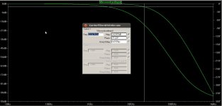
At 20kHz this filter will attentuate the signal approx. 0.7db.
At 300kHz attentuation will be approx. 30db.
-30db is already not much and you will have to check if this is sufficient for your particular measurement equipment.
In case you really need it more sharp, with less impact at 20kHz - I guess you would need to go towards more complicated passive RLC filters (here take care regarding distortion and gain ripple...) or an active Tschebbyscheff filter (again take care with gain ripple and distortion).
In case you want to calculate by hand and want to have it precise without guessing a 'fudge' factor (great wording 😀 ), then you would need to calculate the sequenced slightly loaded frequency depending voltage dividers with Kirchhoff and using imaginary numbers for the impedance of the caps.
Where as
z_cap= 1 / j(2 x pi x f x C)
Unfortunately the resulting math terms describing RC networks with more than 2 capacitors are ugly and tend to hide the goal, except your brain is well trained on exactly such terms and what they mean in the frequency domain.
In the year 2012 it is more practical to look at it as described by KSTR, let a software do the details and just recheck the fundamental fit of the results.
In case you dislike the -3db at 20kHz, I would propose to sequence filters with approx. double pole frequency.
I.e.
47R,22nF
150R,6.8nF
470R, 2.2nF
1500R, 680pF
At 20kHz this filter will attentuate the signal approx. 0.7db.
At 300kHz attentuation will be approx. 30db.
-30db is already not much and you will have to check if this is sufficient for your particular measurement equipment.
In case you really need it more sharp, with less impact at 20kHz - I guess you would need to go towards more complicated passive RLC filters (here take care regarding distortion and gain ripple...) or an active Tschebbyscheff filter (again take care with gain ripple and distortion).
- Status
- Not open for further replies.
- Home
- Amplifiers
- Class D
- Low Pass filters for class-D audio testing??