They are 680uH though.
jcx I do not know much about options and not a designer. I just followed what Ti recommended in their DATA sheet. If someone can come up with a better IV stage I am glad to incorporate it.
jcx I do not know much about options and not a designer. I just followed what Ti recommended in their DATA sheet. If someone can come up with a better IV stage I am glad to incorporate it.
Last edited:
But, even 1.2mA as DAC output is low.
Better talk to BB/TI about that.
@kinku - I used these TDK inductors but found mine were probably fakes. I measured them and binned them according to value (10uH increments) and found they had a bit over the 20% spread. You could get yourself an LCR meter or just order some and tweak the cap values a bit if the FR doesn't look flat enough. Chances are your speakers will have a more irregular FR than the filter even if you build it with the 680uH types without pre-selecting them.
is 10mV an AC , or peak, or peak to peak voltage?
is 1.2mA an AC, or peak, or peak to peak current?
is 60mV an AC , or peak, or peak to peak voltage?
In order they're an RMS voltage, a DC current and a peak-to-peak AC voltage.
Jcx has raised a good point about the noise - the filter I designed to interface to a 16bit DAC. Given that your PCM1704s are around 20bit in terms of noise, it might well be better to design the filter so it gives a bit more voltage swing and thus make the job (noise-wise) of the post-amplifier easier. The inductor values can be scaled up - (TDK make them up to 1.5mH - not sure if Mouser stock those though), the caps would scale down in value proportionately and the I/V resistor increases in proportion to the inductor value increase.
@kinku - I used these TDK inductors but found mine were probably fakes. I measured them and binned them according to value (10uH increments) and found they had a bit over the 20% spread. You could get yourself an LCR meter or just order some and tweak the cap values a bit if the FR doesn't look flat enough. Chances are your speakers will have a more irregular FR than the filter even if you build it with the 680uH types without pre-selecting them.
Gotcha, perhaps I can use 672uH.
What are the cut off frequency, stop band frequency I should shoot for. Do you think I will have enough gain after the passive filter stage if I use the current IV stage?
And what should be the allowable stop band for these application. Why does it have to be cut steep at 20KHz ?
Last edited:
Cut off frequency's a subjective judgement call. I aim for -50dB at 24.1kHz, which is the first frequency for images to appear. With a filter around 11th order, this puts the corner frequency somewhere between 17 and 18kHz. If you want more of the audio band to listen to you can relax the image rejection (which I chose just on a whim) or you can increase the filter order.
As regards the steepness - again its a trade-off. Steeper filters have better rejection but poorer phase response. Eliminating the images improves the dynamics, subjectively, results in a lower perceived noise floor. A shallower filter will probably sound better than no filter at all.
As regards the steepness - again its a trade-off. Steeper filters have better rejection but poorer phase response. Eliminating the images improves the dynamics, subjectively, results in a lower perceived noise floor. A shallower filter will probably sound better than no filter at all.
Last edited:
http://myweb.tiscali.co.uk/g8hqp/audio/CDsample.html
I was reading this article and wondering what is true? Seems like a sharper cut off is not musically pleasant perhaps leaving some images behind would be a better option?
I was reading this article and wondering what is true? Seems like a sharper cut off is not musically pleasant perhaps leaving some images behind would be a better option?
yes, it is +-1.2mApk. Not DC.
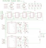
fig5 shows 2k5 as the load that the DAC current is fed into.
The output impedance is specified as 1k.
Why are you feeding into 50r? which limits the V after conversion to +-50mV.
The 2k5 allows +-3V and that is equivalent to the typical CDP output of ~2Vac to 2.2Vac
Obviously I don't understand why you have the 50ohm in there.
Do you want to explain that to someone who does not yet do digital?
Ah then if its a bipolar output (1.2mA in both directions) then my calculations are off (pessimistic) by 6dB. So we'll get 20mVRMS out of the filter with 50ohms as the I/V resistor.
I'm feeding into 50R primarily because that's the input resistance the filter's designed for. But its not a bad choice for this DAC anyway. We could go up a bit before the DAC's output compliance specification comes in to limit us. There are protection diodes which turn on if we let the output wiggle too much - hence a lowish value is called for to avoid distortion (and possibly damaging an expensive DAC).
Where have you gotten 2k5 from? The DAC's compliance spec won't allow a resistor anywhere near that value. The DAC's own output impedance spec isn't really relevant to the choice of I/V resistor.
Copy that - in that application the OPA627 is maintaining a 'virtual earth' (through NFB) at the DAC's Iout pin so there's no violation of the output compliance limit.
Yes, it converts the DAC I to a V
1.2mApk becomes 3Vpk
but you are using 50R and that converts the DAC I of 1.2mApk to a V of 60mVpk
1.2mApk becomes 3Vpk
but you are using 50R and that converts the DAC I of 1.2mApk to a V of 60mVpk
Sorry, can't identify what R you're talking about here. Do you mean the output of the LC filter? If so its the same as the I/V R.
Abrax it seems like passive filter design would need a lot of space in PCB with all those bulky ferrites. If I go active the noise figure comes up to worst case: 35.0u Vp-p (AD FILTER WIZARD). Don't you think the phase response and group delay also need to be considered?
Which ferrites have you found which are bulky? Those TDKs are about 7mm on a side - the DAC+filter board on my blog is circular, about 7cm diameter.. No I don't think phase response and group delay are as important for SQ as bandlimiting the DAC's output. Hence my suggestion of a high order passive filter.
You'd need chokes of a very high value - say 33mH, not impossible but rather impractical. You can't use 2k5 with the PCM1704 directly, you'd need to use opamp I/V. Putting an opamp before the filter rather defeats the purpose of the filter....
- Status
- Not open for further replies.
- Home
- Source & Line
- Analog Line Level
- low pass filter for DAC output