Hello all.
Okay, I've been lucky with trial, and error troubleshooting, and eventually repairing circuits. Don't want to waste anyone's time here with stuff I should already know. But I just can't figure this one out.
Getting weirdness from WT800 in bridge mode.
First ting I did was replace the open 27K feedback resistor that had failed open.
In bridge mode, I'm getting a larger signal on negative side (inverted right channel) than I'm getting from the positive side (non-inverted left channel).
Both right, and left channels are putting out the correct wattage in stereo mode.
Bridge switch seems fine. The R channel input is being muted by JFETS when in bridge mode. Getting signal from L channel output at 12K/27K junction.
When scoping output negative terminal I'm getting 36V RMS before clipping
Positive terminal is reading 22V rms.
At this point, I can apply more signal and get 36V on Pos teminal as well, but the negative side is clipping.
With the above 36/22V RMS scenario, I'm reading 58V across NEG and Positive with DVM.
Obviously, far below the specified 800 watts for bridged into 8 ohm load.
Using electric stove hotplates paralleled to get a perfect 8 ohms.
Hoping someone can see something obvious here.
I appreciate, and humbly await any response to guide me.
Thanks,
Stan
http://schems.com/bmampscom/eden/Eden WT500, WT600, WT800 - Schematic.pdf
Last edited:
Unfortunately, the service docs are a mess (with the power amp from another, presumably similar unit) and do not actually cover the part you are interested in: the resistors involved in BTL operation.
Not really sure how this is even supposed to work; often you have another resistor the same value of the feedback resistor connecting from the other channel to the inverting input (making up an overall inverting amplifier of gain -1), and then the noninverting input is grounded (or muted, as in this case). I can only guess that they have split the extra resistor, grounding it in non-BTL operation.
This would imply that part of the BTL resistor is always there in parallel with the feedback's ground leg. If gain is the same in non-BTL mode, they probably chose ground leg resistors to compensate.
You will have to look for the mysterious BTL resistor - quite possibly a series R-C. It may have drifted, the capacitor may be dried out.
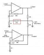
So long as the two resistors feeding back to the right hand amp are equal, the right hand amp will invert 1:1 - its acting to keep the midpoint of those resistors at ground, so that the two
outputs are balanced.
outputs are balanced.
Thanks for the info, gentlemen!
Yes, the schematic is very difficult to make sense out of. Especially for someone like me who is still figuring out how SS power amps work.
Later version of amp is attached below.
Same principle with the 12/27.4K.
I did just solder the 27K on top of open one, but it was measuring in the 6 meg range, so I don't really see a problem there.
Would appreciate any other ideas as to why this isn't balanced.
Stan
Attachments
Well, got the two outputs balanced by using a trim pot to dial in the 27K resistor. 25.6K did the trick
I'm getting 36 RMS before clipping from each waveform with 2 channel scope probes. So would 640 V into 8 ohm load be considered in the ballpark, or is there something else going on?
Measuring more like 60V RMS between +and- from cheap DVM. So probably shouldn't trust that as mush as the Tektronix scope.
Thoughts?
Thanks everyone for the prior replies.
Stan
So the missing resistors were lurking in the power supply section. R8 (12k) + R9 (27k) = R18 (39k), or that's how it should be. So check that 12k, I say.
Then I'm still not sure how R16 in the power amp (another 27k) fits in the picture.
Then I'm still not sure how R16 in the power amp (another 27k) fits in the picture.
- Home
- Amplifiers
- Solid State
- Low output from Eden WT800 in Bridge Mode