Hi all,
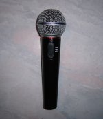
I am rebuilding an electret microphone in which many years ago I used a replacement capsule for Shure SM94. Now I have built a smd circuit on the solder side of a prototype board, but noise is very higher than in the old circuit. At that time I selected 2N5087 among other types a the best ones. Now I used BC860(smd). Do you think BC860(smd) could produce higher noise than 2N5087? BC560 have the same noise?
Thanks,
Gianluca from Roma, Italy
This is the schematic of my version:
Attachments
Last edited:
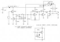
Complete schematic, better quality (I can't edit first post anymore...):This is the schematic of my version:
Attachments
The circuit just looks a little "odd" tbh. Have you tried to draw the circuit out from your old one.
Does it actually work OK apart from the noise ?
Does it actually work OK apart from the noise ?
I have built the old one identical to the schematic I had drawn from the SM94. It had no more noise than SM94.The circuit just looks a little "odd" tbh. Have you tried to draw the circuit out from your old one. Does it actually work OK apart from the noise ?
Today I bought 3 2N5087. I'll replace the 3 BC860 smd and i'll let you know.
Datasheets say BC560 (they should be identical to the smd version BC860) have low noise for source resistance of about 2kOhm; 2N5087 for about 20kOhm... It's very hard to evaluate only on the sheets which one among two transistors will be quieter in a specific circuit...
LED is added by me; 47uF is a one-time voltage doubler making a flash at power on if battery is ok. No visible LEDs can be turned on directly from 1,5V and current drawn by a LED would be much higher than the current drawn by the amplifier.
Q1 is an active load for the FET. His Vce is regulated by supply voltage. Higher voltage gives more dynamic range. 15uF between b-e makes Q1 like a current generator for audio signal, because Vbe, then Ic, is independent from audio signal on the emitter. Q1 is a stable voltage source for polarization, but it has a high impedance for audio signal.
Q2 and Q3 are emitter followers to lower the signal impedance. They are in series for audio, but they have the same polarization (depending on supply voltage).
The BF245A (a current regulator field effect "diode" 1N5304 in the original circuit) with the 270 Ohm resistor is a current regulator set to 1.8mA. Note that required resistor value is different from a single FET to another, first of all because Idss can be very different from one to each other.
Last edited:
Thanks for the explanation... obviously try the other transistors and see.
I'll tell you what puzzled me... and I'm not really familiar with powering mics via a phantom supply but anyway.
Q2 and Q3, it seems really odd to bias both from the same point, Q3 and the 47k tie the base to the same audio input that Q2 is receiving. That's odd 🙂
That was one thing, the other is the 1.5v battery. The fact that it's there I guess means the circuit is intended to run off just that if needed, the Ge diode giving low forward voltage drop. So with no phantom supply the bias for Q1, Q2 and Q3 and their operating point is very transistor dependant as the bias is provided by just a simple "resistor to ground" and not a network setting a defined bias point.
Anyway, there we go 🙂
Q2 and Q3, it seems really odd to bias both from the same point, Q3 and the 47k tie the base to the same audio input that Q2 is receiving.
- Q2 and Q3 are AC-coupled, then they can be biased at the same point. Audio from Q2 via capacitor has low impedance, then it is stronger than the signal via 47k.
- Drop is 240mVThat was one thing, the other is the 1.5v battery. The fact that it's there I guess means the circuit is intended to run off just that if needed, the Ge diode giving low forward voltage drop.
- It works... 🙂So with no phantom supply the bias for Q1, Q2 and Q3 and their operating point is very transistor dependant as the bias is provided by just a simple "resistor to ground" and not a network setting a defined bias point.
Anyway, there we go 🙂
a little odd is that pin 3 is not driven??
I'm thinking the 1.5 battery is the on/off switch... not sure how that works though.
_-_-bear
I'm thinking the 1.5 battery is the on/off switch... not sure how that works though.
_-_-bear
In the original there is a transformer, without the two 2k7 resistors. In my version output is only "impedance balanced", driving only the "+" output (2). "-" output (3) has the same impedance, but there is no signal.a little odd is that pin 3 is not driven??
The two 100 Ohm resistors will be differene, because on the driven side there is also about 40 Ohms output impedance.
Uh?...I'm thinking the 1.5 battery is the on/off switch... not sure how that works though.
The best way to know about different transistors and their noise is by looking at their data sheets. The 2N5087 is an old device, more than 40 years, and was pretty good for its time, but I doubt that an even quieter device would make much difference in noise, as it is probably set with the capsule and input fet.
EUREKA!
It works...
Now, with 3x 2N5087, noise is the same of the original SM94.
A 2-position jumper switches 3 values for C1:
11nF ("Cut", no jumper), 250Hz
61nF ("Mid", pos.1) [11+(100series100)], 50Hz
111nF (Full", pos.2) [11+100], 25Hz
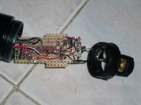
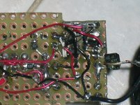
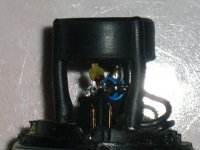
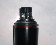
In the first two photos you can see the board with the three BC860 smd, before replacing with 2N5087's.
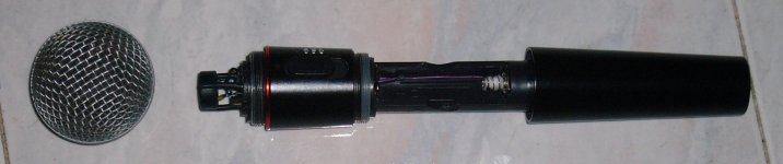
As you can see in the last photo I have added some tulle inside the grill (it's a Shure SM58 grill) to try a better anti-pop. It's hard to put properly the tulle. I have cut it like a Malta cross, but I'm not so satisfied... The best would be a metallic tissue like the one in Sennheiser mics (MD431, MD21, MD421, ...).
It works...
Now, with 3x 2N5087, noise is the same of the original SM94.
A 2-position jumper switches 3 values for C1:
11nF ("Cut", no jumper), 250Hz
61nF ("Mid", pos.1) [11+(100series100)], 50Hz
111nF (Full", pos.2) [11+100], 25Hz
In the first two photos you can see the board with the three BC860 smd, before replacing with 2N5087's.
As you can see in the last photo I have added some tulle inside the grill (it's a Shure SM58 grill) to try a better anti-pop. It's hard to put properly the tulle. I have cut it like a Malta cross, but I'm not so satisfied... The best would be a metallic tissue like the one in Sennheiser mics (MD431, MD21, MD421, ...).
Attachments
-
 P1050599.jpg260.1 KB · Views: 515
 -
 P1050601.jpg250.5 KB · Views: 516
 -
 P1050603.jpg389 KB · Views: 496
 -
 P1050606.jpg462 KB · Views: 155
 -
 P1050605.jpg200.6 KB · Views: 424
 -
 P1050604.jpg360.3 KB · Views: 423
 -
 P1050608.jpg482.8 KB · Views: 172
 -
 P1050609.JPG97.8 KB · Views: 180
 -
 P1050611.jpg461.7 KB · Views: 147
Last edited:
Oh... Before you ask: 🙂
Cotton in the "-" battery spring is to dampen resonances if microphone body is hit or "tap"-ed without a battery in the compartment.
Cotton in the "-" battery spring is to dampen resonances if microphone body is hit or "tap"-ed without a battery in the compartment.
UPDATE:
I've added a big washer of melamine acoustic foam around the legs of the capsule for a better sound, directivity and feedback rejection and two pieces filling volume near the board.
Now filter position "50Hz" has become 100Hz:
29nF ("Mid", pos.1) [11+(22series100)]
I've added also an optional eq LR series 17mH + 330 Ohm between output connector pins 2-3. It softens low-mid band below 3kHz about 5dB. Acoustically it is equivalent to a 5dB gain over 3kHz. I like it.
Sounds good... I'm not much of an expert on mics and using and choosing and so on.
I used an LR combination on a headphone amp for my dad that gives a huge peak in the response around 2 khz. Much easier than using active components and far more effective.
I used an LR combination on a headphone amp for my dad that gives a huge peak in the response around 2 khz. Much easier than using active components and far more effective.
Hi all,
I am rebuilding an electret microphone in which many years ago I used a replacement capsule for Shure SM94.
Congratulations you got the project to work, nice!
Was wondering, where did you get the SM94-replacement capsule ? I have a Shure BG 4.0 here that has a fizzing capsule, might be time for a replacement since the crackles keep going on. Couldn't find a BG 4.0 / 4.1 / SM94 replac. capsule so far. So curious where you got yours.
Thanks!
Peter
I'm sorry for the long delay. I've not visited this forum for a long time...
The man at the audio/music shop ordered a spare capsule for me about 15 years ago...
Gianluca
The man at the audio/music shop ordered a spare capsule for me about 15 years ago...
Gianluca
There is a good reason, why a balancing transformer had been used in the original version of this microphone: in contrast to "impedance balancing" "real" balanced lines have an excellent rejection of interference signals induced to the cable. This allows a microphone to be connected to a line of hundreds of feet in length (essential, if i "snake" is used in a live situation or a large studio with very long cable runs) without being affected by "static" or even reception of a nearby taxi radio etc. For proper impedance balancing the grounded 100 Ohms resistor should be increased to 140 Ohms (not a standard value), or both resistors could be adjusted to 82 Ohms for the "hot" resistor and 120 Ohms for the grounded one. This should improve the "common mode rejection" of a balanced input.
- Status
- Not open for further replies.
- Home
- Source & Line
- Analog Line Level
- Low noise transistors for electret mic