...
Ales, could you give me the (estimated) ground pad area in cm^2? If I have the time, maybe I can calculate some estimated temperatures for certain load-situations... Just a thought.
Thanks
Florian
Sure, single PCB has around 14cm^2 and dual PCB has around 10cm^2. I could also make temperature measurements on different current draws, from 100mA to 1A, steps by 100.
Regards,
Ales
Ah, nice, thanks. 🙂
How would you measure the chip temperature?
Unfortunately only with contact probe. I don't have IR thermometer or thermal camera, which would be really great😉.
Ok, I finally managed to take a closer look at the datasheet.
Two things:
1) You were right Ales. The copper size is big enough so that a larger heatsink should make no difference. (Figure 25) This counts for all groundplane areas of 10cm^2 or larger. I assume the small chip area is the bottleneck for the heat transport here.
2) Equation 8 shows that a theoretical junction temperature of 170 degrees celcius is reached (for 25 degrees ambient temperature, current = 1A) when the dropout is larger than 4.45 Volts. If I understood the formula correctly, this is the absolute maximum for this regulator. Assuming 50°C ambient temperature (which is probably realistic in some cases), we get a maximum dropout voltage of 3.7 Volts, until the thermal protection gets activated.
Here are some calculated maximum dropout voltages Vd,max for conservative 50° case temperature and moderate 100°C junction temperature.
I = 1A, Vd,max = 1.5V
I = 0.5A Vd,max = 3V
I = 0.2A Vd,max = 7,5V
I = 0.1A Vd,max = 15V
Here is still a lot of headroom, because the difference between ambient and junction temperature is only 50°C
Please correct me if I´m wrong...
Thanks
Florian
Florian,
I think your calculations are quite accurate. I just tested temperature and these are the results:
Vin = 14.4V
Vout = 12V
Iout ~ 500mA
Ambient T = 21.2°C
Chip T top = 70.3°C
Chip T bottom = 74.2°C <- right under heatpad
time = 45min <- temperature stabilized after 10min
I will also test it with small heatsink (RAM heatsink for example). I think it may help and it's not just for cosmetics🙄.
Best Regards,
Ales
Well, that fits actually quite nicely.
For Vd=2.4V, you get a deltaT of slightly over 50 degrees.
The datasheet refers only to groundplane areas as heatsink. So a small heatsink attached directly under or on top of the chip might still get temperatures a little lower... (for the sake of longevity)
The lesson learned for me here is that for higher currents, the transformer secondaries should probably be chosen wisely 🙂
Regards
Florian
Just tested the board with small heatsink and there is quite big difference. With same conditions as stated above, the chip temperature on top was 54°C, while heatsink had 41°C. So I will add small heatsinks to all of PCBs.
Best Regards,
Ales
Best Regards,
Ales
@ mravlca,
nice looking white PCBs, where did you order them?
best regards,
hallodeletue
Hi hallodeletue,
These were ordered at dirtypcbs. Service is excellent, PCBs are great, only stop mask and silkscreen sometimes aren't that good as they should be.
One thing I do with all PCBs is that I clean them with isopropanol, flux washes off and it gives the whole PCB shiny effect.
Best Regards,
Ales
looking forward to some boards being available mate!
Hi MisterRogers,
hopefully I will have some available within a month, I am still waiting for some materials.
BR,
Ales
Is the following a similar PSU in design?
4.17uV Ultralow noise DAC power supply regulator +-12/15V 1A - DIYINHK
4.17uV Ultralow noise DAC power supply regulator +-12/15V 1A - DIYINHK
Is the following a similar PSU in design?
4.17uV Ultralow noise DAC power supply regulator +-12/15V 1A - DIYINHK
Yes it is, but these PCB from diyinhk don't have sensing circuit.
heatsink bridge
Hi guys,
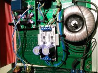
so I found very simple solution how to keep temperature of the regulators low when they output high currents. I mounted PCB on standoffs which are 10mm high and under the regulators I placed two aluminum blocks which are also 10mm thick. To prevent any shortages I placed thermal insulation pads between PCB and aluminum block. You can see in the picture how it's done.
The temperature difference between ambient and chip is around 5°C, driving buffered headphone amplifier. Will test this also with resistive load and exact currents.
Hi guys,
so I found very simple solution how to keep temperature of the regulators low when they output high currents. I mounted PCB on standoffs which are 10mm high and under the regulators I placed two aluminum blocks which are also 10mm thick. To prevent any shortages I placed thermal insulation pads between PCB and aluminum block. You can see in the picture how it's done.
The temperature difference between ambient and chip is around 5°C, driving buffered headphone amplifier. Will test this also with resistive load and exact currents.
Attachments
Hi Mravica,
Thank you for the explanations on my PM. I sent you my PP adress for invoice for 4 single units.
Regards
Eldam
Thank you for the explanations on my PM. I sent you my PP adress for invoice for 4 single units.
Regards
Eldam
Hi Àles,
Receive all the pcbs this morning.🙂
Nice looking and soldering.
Have you please a little "how to" to understand where I can use or not the sensing pins ? I'm totally a beginner whith sense/force connections, even not found any translation in my native language with this technical concept!🙁
Thank you for those cute boards !
Hi Àles,
Receive all the pcbs this morning.🙂
Nice looking and soldering.
Have you please a little "how to" to understand where I can use or not the sensing pins ? I'm totally a beginner whith sense/force connections, even not found any translation in my native language with this technical concept!🙁
Thank you for those cute boards !
Hi Eldam,
please follow link below for more information.
Best regards,
Ales
TPS7A4700 manual
Hi Àles,
Receive all the pcbs this morning.🙂
Nice looking and soldering.
Have you please a little "how to" to understand where I can use or not the sensing pins ? I'm totally a beginner whith sense/force connections, even not found any translation in my native language with this technical concept!🙁
Thank you for those cute boards !
Also if you would like to know about this topology search for Kelvin sense connection. You'll find a lot of information about "sensing".
Best Regards,
Aleš
Thanks Ales for the links and help for googling (usefull 🙂 ... pardon my french 😉 !
i'm choosing the main smoothing cap and my understanding reading the datasheet of Ti TPS74700 is I need a low ESR one to improve the noise sound floor. So I will go for a value like you advise : 3300 uF in the Panasonic FM caps range.
i'm choosing the main smoothing cap and my understanding reading the datasheet of Ti TPS74700 is I need a low ESR one to improve the noise sound floor. So I will go for a value like you advise : 3300 uF in the Panasonic FM caps range.
- Status
- Not open for further replies.
- Home
- Amplifiers
- Power Supplies
- Low noise symmetrical PSU TPS7A4701 and TPS7A3301