Jocko Homo said:Almost all modern circuits place the crystal in the series resonant mode. The confusion arises when you start to specify the frequency.
A crystal that is said to be series resonant has its series resonant mode measured into a resistive load, say 50 ohms.
When you see a crystal with its resonant frequency specified at a parallel load of X pF (usually in the 20 - 32 pF range), the series resonant mode is measured with a load of that specifed capacitance, instead of the resisitive load.
Aren't you a little bit unclear here?
Serie resonance frequency = when the crytal is purely resistive, 10-20 ohms for AT-crystal
Parallel resonance frequency = when the crystal is highly inductive, around Henrys. How much inductive depends on the load capacitnce.
Every crystal has both modes but they can't be tuned to the "wrong" mode. You get very bad Q if a parallel crystal is tuned to series mode and vice versa. If the crystal is made for 4 MHz parallel mode, don't tune it to 4 MHz series mode.
I have practical experince of that. I made long ago a 4.194304 Hz ocsillator with a parallel crystal and put it in a series one. The oscillator became rather sensitive due to much tuning. Without tuning the result was quite OK, but with the wrong frequency. I used it as an 1 Hz oscillator to an ordinary clock.
low output level?
So I fired up my board,
the output looks good, freq looks good, but the output level is only 200-300 mV p2p, it was mentioned earlier that it should be ~1Vrms. I made the following changes:
Freq. ~24Mhz 18pF crystal
C4 =10pF
C3 = 5-18pF
As per Jocko's recommendations:
C1 from 470pF to 220 pF
C2 from 86pF to 33pF
My own doing:
C6 C7 from 18 to 15 pF (all I could get locally)
Q2,Q4 MPS8099
Q1,Q3,Q5 to zetex parts listed previously
Resistor values have all been checked, Vrail ~12V, ~50mA total draw.
Any Ideas?
-Pete Kunz
observations after further playing around...
There appears to be alot of attenuation over the 15 (originally 18)pf capacitors C6, C7. Paralleling another 15 to each brings the signal level back up... Earlier schematics from other threads:
http://www.diyaudio.com/forums/showthread.php?threadid=3746&highlight=oscillator
show 47pf values for the blocking caps? Is there a reason they were reduced for this design, and is increasing the value a proper solution to the low output I see with the spec'd values?
Thanks,
Pete Kunz
I'm afraid I don't understand the situation with the crystal here either. My source for crystals (Digi-Key, naturally) has 24.576MHz crystal specified for series load. I'll need to read up on crystals before I understand what that means for this circuit.
If I reduce this to the equivalent circuit, it starts to look like the 24.576MHz crystal with 36pF caps to ground on either side. So the crystal would be operating in parallel mode, and therefore going approximately 11kHz faster than spec.
Mine my well be that far off, I've only had a chance to look at it so far on a 20Mhz ASO (the crystal is a 24.576MHz 18pf parallel from digikey), the 100Mhz DSO is in another lab right now.
-Pete Kunz
-Pete Kunz
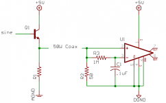
While looking for something else, I found this link for a high performance sine to square converter.
Hopefully this satisfies "exotic" 😀
mlloyd1
Hopefully this satisfies "exotic" 😀
mlloyd1
Jocko Homo said:....
The first go-round uses a '04 inverter set for a gain of 4 to square it up. Maybe next time I'll come up with something more exotic.
Jocko
Hmmm... sounds like the audio definition of "exotic" to me 🙂
jwb said:Using a transformer to square a sine wave is silly and expensive ....
- Status
- Not open for further replies.
- Home
- Source & Line
- Digital Source
- Low-noise oscillator