Hi DF96,
I use the parallel connection of a 1 Mohm and a 47 kohm resistor as a "calibrated noise source" and assume that the valve noise can be represented with sufficient accuracy with just an equivalent input noise voltage source. This is obviously not true for the Amperex device with 1 uA grid current, which is why I didn't bother to measure its noise.
So what I measure is:
-Noise of the anode bias resistor, amplifier and laptop with the valve supplies switched off
-Noise of the valve plus the anode bias resistor, amplifier and laptop with the grid shorted to ground
-Noise of 44890 ohm (47 kohm//1 Mohm) plus the valve plus the anode bias resistor, amplifier and laptop, the 44890 ohm being connected between grid and ground
The thermal noise of 44890 ohm is known, so with a bit of straightforward mathematics I can calculate the equivalent input noise voltage of the valve from these results.
The impression I get from my measurement results is that white noise drops with anode current, whereas the 1/f noise has a minimum somewhere around 2.5 mA anode current. That white noise drops monotonically while 1/f has a minimum is as expected from theory. But I'll do some more spot noise measurements to see whether I'm right.
Best regards,
Marcel van de Gevel
Assuming a typical triode-connected gm of 2.5mA/V, Req should be around 1K which will give noise of 4nV/sqrt(Hz). Your figures are about 6dB above this, although flicker noise makes a contribution at low frequencies. It might be possible to estimate the 1/f corner frequency, somewhere around 1kHz.
Interesting results!
Interesting results!
Additional spot noise values, second Trigon device (actually the old recordings processed differently):
100 Hz to 150 Hz:
(193.5 uA: 22.53 nV/sqrt(Hz))
(298 uA: 20.86 nV/sqrt(Hz))
907 uA: 22.02 nV/sqrt(Hz)
2073 uA: 33.16 nV/sqrt(Hz)
3960 uA: 43.81 nV/sqrt(Hz)
10 kHz to 12 kHz:
907 uA: 9.75 nV/sqrt(Hz)
2073 uA: 5.77 nV/sqrt(Hz)
3960 uA: 5.68 nV/sqrt(Hz)
In retrospect I don't trust the measurements at 193.5 uA and 298 uA: I heard sounds that didn't sound like noise, so maybe I was measuring mains voltage fluctuations and/or microphony. Also the 298 uA 100 Hz to 150 Hz value makes no sense when you compare it to the 20 Hz to 20 kHz value.
Ignoring these values, the general trend is that between 907 uA and 3960 uA, white noise gets less with increasing current while 1/f noise increases. Apparently the 1/f noise minimum for Trigon EF86 number 2 occurs at an anode current of less than 907 uA.
For the Amperex devices the low-frequency noise increased very rapidly below 1 mA. I didn't measure that, but I could hear it very clearly.
Hi,
I've remeasured the triode-connected Trigon EF86 valve at currents below 1 mA and I've reprocessed the old recordings for 2 mA and 4 mA. The latest results are:
Flat, 20 Hz to 20 kHz:
199 uA: 16.45 nV/sqrt(Hz)
297 uA: 13.87 nV/sqrt(Hz)
891.5 uA: 9.045 nV/sqrt(Hz)
2073 uA: 7.384 nV/sqrt(Hz)
3960 uA: 8.541 nV/sqrt(Hz)
A-weighted, 20 Hz to 20 kHz:
199 uA: 15.73 nV/sqrt(Hz)
297 uA: 13.11 nV/sqrt(Hz)
891.5 uA: 8.438 nV/sqrt(Hz)
2073 uA: 6.482 nV/sqrt(Hz)
3960 uA: 6.357 nV/sqrt(Hz)
100 Hz to 300 Hz:
199 uA: 19.9 nV/sqrt(Hz)
297 uA: 20.02 nV/sqrt(Hz)
891.5 uA: 20.8 nV/sqrt(Hz)
2073 uA: 26.27 nV/sqrt(Hz)
3960 uA: 38.03 nV/sqrt(Hz)
1 kHz to 1.2 kHz:
199 uA: 16.32 nV/sqrt(Hz)
297 uA: 14.56 nV/sqrt(Hz)
891.5 uA: 10.01 nV/sqrt(Hz)
2073 uA: 9.062 nV/sqrt(Hz)
3960 uA: 8.871 nV/sqrt(Hz)
10 kHz to 12 kHz:
199 uA: 16.21 nV/sqrt(Hz)
297 uA: 12.89 nV/sqrt(Hz)
891.5 uA: 8.205 nV/sqrt(Hz)
2073 uA: 5.798 nV/sqrt(Hz)
3960 uA: 5.597 nV/sqrt(Hz)
Needless to say, I haven't a clue how accurate these measurements are.
At least you clearly see the trends: white noise gets less with increasing bias current while excess noise increases with increasing current. The total noise around 200 Hz stays more or less constant up to about 1 mA and then increases. The optimal current for audio use is in the range of 2 mA to 4 mA, presumably on the lower side of this range for RIAA amplifiers as they have more gain for lower frequencies.
The trend for 1/f noise below 1 mA was very different on the crappy Amperex devices, there it increased enormously below a certain current. Presumably this was the island effect that Van der Ziel wrote about.
My measurement procedure is now:
-Switch off all equipment that you don't need, preferably by unplugging it, to minimise interference
-Record the noise with the valve switched off
-Record the noise at various bias current settings with grid grounded
-Record the noise at various bias current settings with grid connected to a known resistor that is used as a predictable noise source (44890 ohm for the old measurements, 20 kohm +/- 1 % for the newer measurements)
-Use a comb filter in GoldWave to suppress 50 Hz mains hum and its harmonics (wave👎-wave(n+882) at 44.1 kHz sample rate)
-Use a steep 20 Hz highpass to remove any subsonics related to mains voltage variations (20 Hz, steepness=20 in GoldWave, which actually means a 40th order filter)
-Listen very carefully to each recording and select a part without any noises due to microphony and thermal expansion, the neighbour's GSM telephone, ticks or anything else that is not noise
-Maximise the level and write down how much GoldWave has increased the level
-Measure the RMS level with GoldWave's "Volume Match" function. Volume Match determines the RMS value but neglects anything below a certain threshold, hence the need to first maximise the level to get an accurate result.
-For the spot noise measurements, bandpass filter the signal, maximise the level and write down how much GoldWave has increased it, cut off a small part from the beginning because the bandpass filter needs some time to settle, use Volume Match again to measure the RMS value. Don't make the measurement bandwidth too narrow if you have only short sound fragments left.
-Use some straightforward mathematics and a spreadsheet to correct for the measurement amplifier noise and to determine the valve noise by comparing it to the known noise from the resistor (assuming that the valve has only equivalent input voltage noise, no input current noise).
Best regards,
Marcel
Last edited:
Hello Richy,
Thanks for the interesting link!
I'm surprised that Standard Telephones and Cables Pty Ltd blaims the leakage of the mica insulators for the spread on the noise, particularly at a source impedance as low as 100 kohm. According to Van der Ziel current noise due to leakage is usually negligible except when unusually high impedances are used, like in electrometer circuits (or condenser microphone amplifiers). Besides, he attributes the leakage to electrons from the cathode being picked up by the grid, electrons being emitted from the grid because of high grid temperature or light falling on the grid, and to collision ionisation due to traces of gas. So basically anything you can think of except the mica insulators.
Best regards,
Marcel
By the way, according to Van der Ziel collision ionisation due to small traces of gas can also increase the white voltage noise enormously (which would be visible at low source impedances), even at small grid currents.
"The positive ions, however, moving through the potential minimum with low speed, reduce the space charge and thus give rise to a large temporary increase in anode current. The original current fluctuation thus becomes amplified by a factor mu_0 which is rather large (mu_0=10 or more)."
He shows a measured graph taken from B. J. Thompson and D. O. North, RCA review, vol. 5, nr. 371, 1941. For the specific valve that they measured a gas pressure giving 1 uA of grid current gave an extra noise of sqrt(2q*4 mA)~=35.8 pA/sqrt(Hz) at the anode. At a transconductance of (say) 2.5 mA/V that would correspond to 14.3 nV/sqrt(Hz) equivalent input noise voltage.
Lo noise valves/tubes
Hi all,
Another couple to chuck into the equation are the Brimar 6BR7 and 6BS7, Which I see someone has already commented on the 6BR7.
I believe the 6BS7 was specifically for instrumentation as it has a g1 top cap.
John Caswell
Hi all,
Another couple to chuck into the equation are the Brimar 6BR7 and 6BS7, Which I see someone has already commented on the 6BR7.
I believe the 6BS7 was specifically for instrumentation as it has a g1 top cap.
John Caswell
Last edited:
I thought it was rather detailed already...
Anyway, attached is the schematic of my test common-cathode stage. The output goes to a 100 times amplifier with an NE5534A. The output of the NE5534A goes to a line input of an Asus Z9200U laptop computer and to an A-weighting filter, the output of which goes to the other channel of the laptop line input. The processing done with GoldWave and Excel is already explained in this thread. See also Linear Audio September 2012.
Anyway, attached is the schematic of my test common-cathode stage. The output goes to a 100 times amplifier with an NE5534A. The output of the NE5534A goes to a line input of an Asus Z9200U laptop computer and to an A-weighting filter, the output of which goes to the other channel of the laptop line input. The processing done with GoldWave and Excel is already explained in this thread. See also Linear Audio September 2012.
Attachments
MarcelvdG,
thanks for your answer. I'm thinking about to make (one more time) a noise measuring set-up, but this time, in a more "permanent" basis.
I have done a well power supply for one of my phono stages, and a pair of Linear Technology LT1115 op amps, that have a very good noise figure.
For measuring purposes, my National VP-7720A could be very suitable.
Cheers !
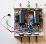
In the meanwhile, I have attached a picture of a module that I have built some years ago, and I will use it again, for my "noise-measurements-set-up".
This module have 3 selectors for the gain: the central one have 5 position: 40, 45, 50, 55 60 dB and acts simultaneously for the two channels. The other two selectors, acts one for the left channel and the other for the right one. In this case, they have 4 positions with increments of 1 dB. (0, 1, 2 and 3 dB). This technique is very useful for to use it as "balance" control, for to compensate differences between channels in some cartridges.
Anyway, I will use this module as "noise amplifier". (using only the op amp stage)
cheers!
Attachments
For low microphonic I have some other missile-rocket-science tubes. I won't name them, because I am going to buy supply for myself, then reveal all details.
Here you go:
planar triode 6S17K-V with 8 micron grid.
gm = 14 mA/V, mu = ~150, designed for 10 g vibration, or up to 500 g acceleration.
Yess, a killer front-ed tube for microphone and phono preamps!Yep, tested it. A great tube indeed:
diyAudio - View Single Post - GS-4V High-mu russian triode for RIAA preamp
The trick is, the grid is so close to cathode so it better works with input transformer, and biased by grid leak resistor and own input current, while cathode firmly sits on the ground.
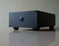
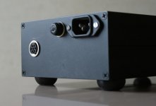
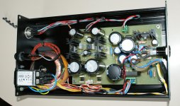
Now, I just have finished to put the power supply into a decent box. Now, I will build some sort of shielded container for the circuits and the "Device Under Test" (DUT). I have not idea how to do it until now, but I will found some cheap solution.
By the way, I'm thinking to use LabView for to make all the signal (noise, actually) analysis and presentation, but I'm new in LabView. Some idea ?
I would like to purchase some good russian valves, but I have seen that all of them (at reasonable prices) are from the outside of the EU. Somebody knows an EU provider ?
Cheers !
Attachments
Yess, a killer front-ed tube for microphone and phono preamps!
The trick is, the grid is so close to cathode so it better works with input transformer, and biased by grid leak resistor and own input current, while cathode firmly sits on the ground.
Hi Anatoliy,
Do you have grid current information from the datasheet to estimate the value of the grid leak resistor?
Thanks
Ale
No, it is not specified, and varies from tube to tube. They did not need high resistances in grids, for intended application in rockets at UHF.
- Status
- Not open for further replies.
- Home
- Amplifiers
- Tubes / Valves
- Low noise, low microphony, low hum valves


