I've built an external PSU to power a preamplifier.
The preamp doesn't have a great deal of gain (x2.2) however when I look at the FFT spectrum, I see a very low level 50Hz hump.
Now, this is totally inaudible (it's approx -135dB) however...
If I change out the transformer, I can reduce the level by about 6 - 10dB, so I'm just curious to know if anybody has any idea how this hump is being induced?
I've experimented with various rectification methods, half wave, full wave, bi phase full wave etc. but the half wave makes it worse (as expected) but the other two make no difference, and the only thing that imprives matters is swapping the transformer.
I've tried various transformers, some reduce the bump to around -147dB, the others just leave it at -135dB.
Increasing smoothing cap value makes no difference. The PSU is using a standard LM317 / 337 setup.
Could this be some kind of electrostatic coupling between the windings?
NOTE: This is not an earth loop, or even earth / ground related.
Last edited:
Well, I'd say that it may be that the 50Hz could be induced by the primary/secondary wiring that is in the close proximity to the circuit parts (or wiring) after the rectifier. I'd try to take the transformer outside and away from the DC circuit and measure again. Try to shield the transformer maybe...
BTW, you didn't mention what kind of transformers you tried. EI, R core, toroidal... If I recall correctly, the EI core transformer (unshielded) might have the higher level of magnetic field escaping the core, bit I may be wrong.
If you only have EI core transformers to work with, try different orientations of it in the enclosure and measure then.
Good luck in solving this issue!
<snip>
BTW, you didn't mention what kind of transformers you tried. EI, R core, toroidal... If I recall correctly, the EI core transformer (unshielded) might have the higher level of magnetic field escaping the core, bit I may be wrong.
If you only have EI core transformers to work with, try different orientations of it in the enclosure and measure then.
Good luck in solving this issue!
I've been using both toroidal and EI core types and some of the toroidals were the worst!
I have also tried mechanical isolation, e.g. moving the transformer further away from the DC board, tried different grounding configurations - in fact I think I've tried just about everything!
I've also tried housing the whole thing in a shielded box, but that doesn't help either.
The last thing I can think of is poor quality shielding (or electrostatic isolation) between the windings on the transformers I've tried.
If you are using a full wave bridge the hump should be 100Hertz not 50. Since its 50 Hertz its picking up the hum from either your home building or transformer.
Try moving the transformer and power supply away from your circuit. Try powering your circuit with a couple of 9 volt batteries. Take a FFT measurement with the input leads of your circuit shorted. Take a FFT measurement of a plain 100k resistor.
I had an annoying oscillation on a preamp of around 120khz. Nothing seemed to make it go away. The fix was to remove the CFL lamp in the ceiling.
I've tried all the above - by process of elimination, it has to be the transformer causing the issue.
If I power the circuit with batteries it's clean, which proves there is a PSU issue.
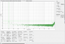
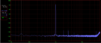
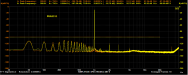
I've attached a spectrum to show what it looks like with the worst transformer.
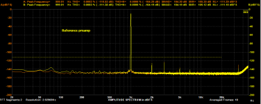
Change to another transformer, and the hump @49.8Hz drops from -130dB to around -148dB - quite a significant drop!
Sorry the screenshots are from two different programs, but you can see what I mean.
If I power the circuit with batteries it's clean, which proves there is a PSU issue.
I've attached a spectrum to show what it looks like with the worst transformer.
Change to another transformer, and the hump @49.8Hz drops from -130dB to around -148dB - quite a significant drop!
Sorry the screenshots are from two different programs, but you can see what I mean.
Attachments
Some years ago I modified a MusicalFidelity pre-amp. As I did not find any "wrong" parts on the PCB, I concentrated on the power supply, which was inside the small pre. The stabilized +- 12 volt (or so) looked really bad.
So I decided to go external and place the power supply in a separate box. I experimented and in the end got a completely clean voltage. The best effect had a coil after the first row of caps. This C-L-C filter removed the hard ripple. Then I tried all kind of capacitors from my, at that time huge supply (we once had the luck to get the garbage bin when Phillips closed some electronic lab in Hamburg, Germany).
In the end some combination of tantalum, electrolitc and some film /foil capacitors did the trick and not even any little sprite was dancing on the supply. It was really interesting, how some cap´s removed spikes, while others, of compare able capacity, but from other brand/ construction, didn´t. I think in the end the dual supply had about eight or ten different caps per side.
The last problem was getting the clean voltage into the pre-amp, as a simple 3-pole wire picked up hum and induced dirt. I solved this by twisting three wires for +-ground together and then screening them. Shrink tube held the construct together. The screen was only grounded at the power supply side.
I think the pre-amp sounded much more "non existing"in the chain, after the cure, but that is subjective.
Anyway, it was just the same as your quest, I wanted to get even the last little spike away. So I understand why you are hunting for the in audible 50 Hz.
Maybe try the inductor, you will be surprised how the rectified voltage looks after the coil. The hum will be down so far at the start of your circuit, you should see it in the end.
PS take as much mHenry you can fit /find, more is better, a little resistance of the coil, maybe up to 10 Ohm, might help as long as the load fits.
Last edited:
...any idea how this hump is being induced?...
Any room which has power in it, has hum in it. Both from wall-wires and from transformers.
You have a specific transformer which hums more than another. OK. Take the good transformer and its rectifier/caps, and move it away. Hum goes down to a point. Until you reach room hum level.
A tighter case may reduce this more.
Putting the rig on batteries and taking it in the woods a mile south of my house would really reduce hum. (Bring your boots and mosquito spray.) OTOH going north a mile gets you away from house-wires but you near a 100,000VAC transmission line through those woods.
-136dB is totally "ZERO". It is 40dB lower than digital "noise". The Fletcher-Munson rise at 50/60Hz is quite large, your ear discounts small bass (else your own footsteps would be disturbing). This is pinhead angel counting.
@Turbowatch2 - useful info thanks.
I realise just how low this hum is and it's not really an issue for me - I was just trying to understand why a transformer could make such a difference.
I have tried running it on batteries and the hump disappears completely, so hum in the room does not seem to be an issue. I seem to be quite lucky, in that the radiated mains fields in my house seem to be quite low.
<snip>
-136dB is totally "ZERO". It is 40dB lower than digital "noise". The Fletcher-Munson rise at 50/60Hz is quite large, your ear discounts small bass (else your own footsteps would be disturbing). This is pinhead angel counting.
I realise just how low this hum is and it's not really an issue for me - I was just trying to understand why a transformer could make such a difference.
I have tried running it on batteries and the hump disappears completely, so hum in the room does not seem to be an issue. I seem to be quite lucky, in that the radiated mains fields in my house seem to be quite low.
Yes, but it doesn't prove the issue is conducted, which if true, means it can not be remedied with additional filtering or regulation.If I power the circuit with batteries it's clean, which proves there is a PSU issue.
If the powered but unloaded PSU, in the same proximity and orientation to the amp, does not produce the symptom, then chances are that it will if you sub in a dummy load that matches the current drain of the preamp.
Those low frequency, low harmonic content magnetic waves are coming from somewhere and the power transformer is the likely culprit.
Cheers
Last edited:
<snip>
Those low frequency, low harmonic content magnetic waves are coming from somewhere and the power transformer is the likely culprit.
Cheers
I tried locating the PSU several feet away, and no difference.
So ultimately - I feel it has to be a transformer issue (given that changing to another transformer reduces the hump), but that's where my understanding ends, and I can only conclude that there is some electrostatic coupling or similar.
Something I also later discovered, is that touching the heatsink of the regulator induces even more hum, which I didn't expect.
Another idea I had was a small value cap to mains earth from the (-) of the PSU, although I can't see how that would help as it would only have an effect at high frequencies.
Your hunch was probably right. Every transformer has some capacitive coupling between primary and secondary, and on larger ones (think integrated / power amp) it's enough for manufacturers to go to the trouble of including shield windings (to be conected to secondary-side ground) if they are to be used in IEC Class II devices. (When trying to obtain such a transformer, you may have the best luck looking for one intended for medical applications, some of which have strict limits when it comes to leakage current.) Usually reversing L and N will also make a difference, as there often is more coupling from one end of the primary to secondary. This can be almost a 10:1 ratio at times, so always try both orientations to avoid mixed fruit basket type comparisons.
Since we are usually talking double or triple digit pF of coupling capacitance, your small capacitor to PE (which I assume means 1-100 nF) would in fact make a difference. It does form a bit of a ground loop, of course, so if you overdo it you'll get more hum rather than less.
The only reason why you are even seeing the effect is your measurement system being earthed, so mains transformer leakage currents will travel along the ground connection which has a very small but finite resistance.
I've built an external PSU to power a preamplifier.
The preamp doesn't have a great deal of gain (x2.2) however when I look at the FFT spectrum, I see a very low level 50Hz hump.
Now, this is totally inaudible (it's approx -135dB) however...
Hi ! would you please mind sharing the PS design/parts used/pics ?

i have a preamp with noise at -80dB ... and i am willing to learn how to improve this.
The spectrum shows both 50Hz and harmonics and high frequency noise
To be precise ... the measurements come from the web.
I think that the amp circuit must have low PSRR ... unfortunately
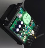
I did not peep inside ... i will do this weekend and take some pics ... for now this is a pic from the web
I do no like very much that green rounded thing ... and actually i would like to replace it with a pcb mount unit with better specs and maybe more noise filtering effect
Any advice would be very much welcome and appreciated
Thanks a lot.
Attachments
Last edited:
and this is the noise spectrum
Review and Measurements of Weiliang Volume Control | Audio Science Review (ASR) Forum
not a nice view indeed ... ok i will short the preamp inputs and listen very close to the speakers
Just to check the noise audibility ...
... i have not done this yet.
Still not the best noise spectrum around.
Review and Measurements of Weiliang Volume Control | Audio Science Review (ASR) Forum
An externally hosted image should be here but it was not working when we last tested it.
not a nice view indeed ... ok i will short the preamp inputs and listen very close to the speakers
Just to check the noise audibility ...
... i have not done this yet.
Still not the best noise spectrum around.
Last edited:
The spectrum shows both 50Hz and harmonics and high frequency noise
To be precise ... the measurements come from the web.
I think that the amp circuit must have low PSRR ... unfortunately
I saw the review on AudioScienceReview - not nice.
There's not a lot you can do with that, but sell it on and buy something better I'm afraid.
They have crammed far too much into a small space, and that's why you get that massive 50Hz peak.
I built a preamp based on that PGA chip and I was not impressed with the performance.
You need to edit your last post to fix the missing image by the way - ideally you should have downloaded the image, and then upload it to DIY Audio.
Hi ! thank you sincerely for your kind and valuable reply.
well that is not a big of an issue ... i can take something out from the box and place it in another one ... that is not a big deal. However i am doubtful about the green mains transformer quality ... ... imhe a transformer with split windings has usually much better mains noise rejection especially in the high Hz range, also plaguing the spectrum ... assumed that the noise comes from the mains of course and is not generated by the voltage regulators ... i will have a better look inside the unti soon to check the actual parts used.
Given the very low price they cannot be top quality.
Anyway i am willing to invest in the modding.
The sound is already quite clean. I am looking for a cheap but decent remote controlled volume solution.
Classe Audio have adopted it for their TOTL preamp ... and the measurements are astonishing
I think that the PSRR of the chip, that i cannot find in the datasheet, must not be that high.
So the secret for nice performance could lie in the design and execution of the power supply.
Thanks again and kind regards,
gino
I saw the review on AudioScienceReview - not nice. There's not a lot you can do with that, but sell it on and buy something better I'm afraid. They have crammed far too much into a small space, and that's why you get that massive 50Hz peak.
well that is not a big of an issue ... i can take something out from the box and place it in another one ... that is not a big deal. However i am doubtful about the green mains transformer quality ... ... imhe a transformer with split windings has usually much better mains noise rejection especially in the high Hz range, also plaguing the spectrum ... assumed that the noise comes from the mains of course and is not generated by the voltage regulators ... i will have a better look inside the unti soon to check the actual parts used.
Given the very low price they cannot be top quality.
Anyway i am willing to invest in the modding.
The sound is already quite clean. I am looking for a cheap but decent remote controlled volume solution.
from what i understand the chip is very very good the actual performances depending on its implementation.I built a preamp based on that PGA chip and I was not impressed with the performance.
Classe Audio have adopted it for their TOTL preamp ... and the measurements are astonishing
I think that the PSRR of the chip, that i cannot find in the datasheet, must not be that high.
So the secret for nice performance could lie in the design and execution of the power supply.
too late i am afraid ... i cannot edit the old message anymore. I can only apologize.You need to edit your last post to fix the missing image by the way - ideally you should have downloaded the image, and then upload it to DIY Audio.
Thanks again and kind regards,
gino
Last edited:
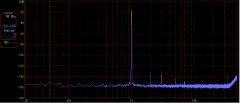
I measured my PGA2311 (not 2310 - note) and it's not pretty.
I suspect that the PCB layout in these Chinese kits may not be optimum - or something...
I have modded mine with extra caps to try and clean it up a bit, and it did help but not by much.
Note that the THD is not that bad - but the noise is not good. The THD also increases with lower levels.
I suspect that the PCB layout in these Chinese kits may not be optimum - or something...
I have modded mine with extra caps to try and clean it up a bit, and it did help but not by much.
Note that the THD is not that bad - but the noise is not good. The THD also increases with lower levels.
Attachments
I measured my PGA2311 (not 2310 - note) and it's not pretty.
The datasheet of the 2310 looks quite ok ... i guess this is also a merit of the evaluation board and power supply used to produce it.
http://www.ti.com/lit/gpn/pga2310
just swapping the green thing and maybe supply caps with very good ones should improve things a bit. I do not know how much because i cannot have measurement tools.I suspect that the PCB layout in these Chinese kits may not be optimum - or something...
which power transformer, regulators and caps have you actually used ?I have modded mine with extra caps to try and clean it up a bit, and it did help but not by much.
parts from China sometimes are even fake ... surely not top quality in the specific case
your unit performance looks much better anyway ... i would be more than satisfied with that. Of course the reference preamp is in another league ...Note that the THD is not that bad - but the noise is not good. The THD also increases with lower levels.
But i need a remote control badly ... i am getting heavier day by day
and lazy
Last edited:
I bought a transformer from a local supplier and it is a reputable brand.
My caps were also purchased locally, and are known good quality parts.
My preamp is remote controlled, I use an Arduino and an Alps blue motorised pot.
It's interesting to note that I see the same spikes in the Spectrum analysis, as Amir did on the Audio Review site.
My caps were also purchased locally, and are known good quality parts.
My preamp is remote controlled, I use an Arduino and an Alps blue motorised pot.
It's interesting to note that I see the same spikes in the Spectrum analysis, as Amir did on the Audio Review site.
- Status
- This old topic is closed. If you want to reopen this topic, contact a moderator using the "Report Post" button.
- Home
- Amplifiers
- Power Supplies
- Low level 50Hz hump in FFT transformer related.