Doesn't this give you the chance to remove the inductor from the output and use the inductance of the resistor (which is there anyway) instead?
Rundmaus
No it doesn't. We want an L with little R so that the impedance at low frequency remains low.
That is on top of what Keantoken has said (I have just read that).
Last edited:
An inductor wound with resistance wire is almost guaranteed to be lossy.HiFiNutNut said:I wouldn't mind if they were lossy inductors (working like ferrite?) but how do I know?
An inductor wound with resistance wire is almost guaranteed to be lossy.
Interesting. I have these so called non-inductive ceramic wirewound 0.22R resistors I bought for the LMOSFET source resistors with 0.2uH indcutance. This is the lowest inductance I have measured with 5W+ WW resistors. Would you use it in your power amps? I am worried that 0.2uH is too high.
Yes, but not for audio. It was the flat film type resistor, about 1cm2 in size. I epoxied it to the chassis for cooling. Works pretty well. As a source resistor, on second thought, maybe the capacitance could be a problem.
Across a 0.33R resistor, even something like 10nF might be okay. Remember these resistors are in series with the load; it's capacitances in parallel with the load which are the biggest problem for stability.
I am having a hard time finding low inductance through hole resistors.
I have a cheap LCR meter that shows inductance as small as 0.1uH. When I measure, I always measure the value then deduct the value from the measurement of a short at the time of the measurement. I think the values I get should be accurate.
Bill
It is simple enough to make a resistor which is in the sub 100 picohenry or so range. The problem stems in how to measure without error as DF96 has pointed out, and how to apply it.
If the through holes are a distance apart, you can never obtain an inductance value below that of a wire bridging that distance with a single element. Paralleling multiple elements does increase the reluctance path, so the DC inductance will drop, but proximity effects will kill this as frequency rises. The current will distribute unevenly in it's attempt at following the path of least reactance.
I make resistors in the 100 pH range by interleaving many axial 1/4 watt metal films. However, I am unable to verify inductance below 250 pH due to physical limitations. I suspect that may be good enough for you. The value of resistance is easy to get from 100 milliohms out to tens of kOhms, the worst part is buying 40 or 80 one percenters from mouser or digikey.
It's easy enough to do, I guess I'll have to pop a sequence of pics into a new gallery, I don't have them where I type at the moment.
Let me know if you're interested.
jn
It is simple enough to make a resistor which is in the sub 100 picohenry or so range...Let me know if you're interested.
jn
That would be very interesting. I'd love to see your photos!
Last edited:
That would be very interesting. I'd love to see your photos!
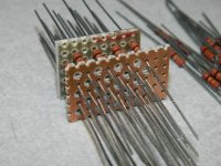
no prob. The first two are assembly of the resistor. It is comprised of three plates. The bottom plate all the resistors are soldered to. The middle plate has every other hole being soldered to, the rest pass through. The top plate has half the resistors soldered to it.
The first pic is a trial fit and photo op.
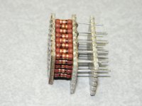
The second pic shows all the resistors soldered to the left side plate, and half of them soldered to the middle plate. The other half are passed through, and will be soldered to the right hand plate.
The current flows in the right hand plate, goes down half the resistors to the bottom plate, then turns around and goes through the other half of the resistors, but do so through the first set of resistors.
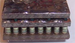
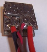
The 3rd and 4th pic show the completed assembly without then with leads.
If you tried to measure the inductance of this puppy, most of the reading will be the inductance from the edge of the assembly to the center. The current passes through itself in the resistive bulk, so that portion of the inductance is very low.
jn
Attachments
Last edited:
who in the world
would use 40 1/4 W axial resistors and worry about sub nH?
jus asking
Me.
Next question?😀
Sometimes I need to measure high rate of change currents with a very low resistor, and cannot allow the inductance of the resistor to get in the way. As the resistor value gets lower, the inductance will cause proportionally higher errors.
jn
The current flows in the right hand plate, goes down half the resistors to the bottom plate, then turns around and goes through the other half of the resistors, but do so through the first set of resistors.
nice, just like x2y caps
An inductor wound with resistance wire is almost guaranteed to be lossy.
That certainly makes sense. However, for a 0.22R wirewound resistor it must be "lossy" but not sufficiently "lossy". 😀
no prob. The first two are assembly of the resistor. It is comprised of three plates. The bottom plate all the resistors are soldered to. The middle plate has every other hole being soldered to, the rest pass through. The top plate has half the resistors soldered to it.
The first pic is a trial fit and photo op.
The second pic shows all the resistors soldered to the left side plate, and half of them soldered to the middle plate. The other half are passed through, and will be soldered to the right hand plate.
The current flows in the right hand plate, goes down half the resistors to the bottom plate, then turns around and goes through the other half of the resistors, but do so through the first set of resistors.
The 3rd and 4th pic show the completed assembly without then with leads.
If you tried to measure the inductance of this puppy, most of the reading will be the inductance from the edge of the assembly to the center. The current passes through itself in the resistive bulk, so that portion of the inductance is very low.
jn
Brilliant!!! This should be a Guinness World Record. 😀
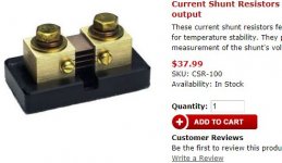
I am sure soldering 40 resistors to make a single resistor can work like a dream but unless I want to build a rocket or something I am not prepared to go that length, given that I can find some SMD power resistors that has virtually no inductance, such as the link I posted earlier.
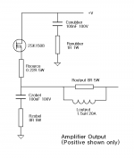
Anyway, I used Microsoft Paint to draw up a simple schematic below which represents the most typical power amplifier output.
I think it is to forum members' benefit if we can come up with some of the best choices of parts with part numbers (e.g. digkey, mouser, farnell) for this output stage at the end of this thread.
I think for Rsource, Rzobel and Rsnubber, we must find resistors with as low inductance as possible. For Routput, high inductance is not a problem.
Similarly, Csnubber and Czobel should be low ESL type capacitors.
Do you agree?
Attachments
First, Source / Emitter resistor:
http://www.vishay.com/docs/31059/wsrhigh.pdf
This is rated 5W 0.2R. SMD. It has 0.5 to 5nH inductance. For 10+ it is $2.373 each at Digikey WSRC-.2CT-ND. Manufacturer part number: WSR5R2000FEA. Materials: metal element / power metal strip.
I have never heard of this material. What about noise, etc? Is it good?
Zobel and output resistors:
http://media.digikey.com/pdf/Data Sheets/Susumu PDFs/CP_2512_S Series.pdf
This is small SMD 10R only up to 16W. It does not mention inductance in the datasheet. For 10+ it is $2.455 each at Digikey: CPA25Q10.0CT-ND. Manufacturer part number: CPA2512Q10R0FS-T10. Materials: thin film.
http://www.bourns.com/data/global/pdfs/PWR263S-20.pdf
This is SMD requiring heatsink pad (capacitance to ground). Available values 7.5R and 10R. 20W. Inductance up to 0.1uH. Materials: thick film.
http://www.seielect.com/catalog/SEI-HPC.pdf
This is SMD without external heatsink. Inductance < 2nH. 8.2R. Thick film.
1R Snubber resistors:
I found a lot of thin and thick film SMD 1R resistors in Digikey's catelogue but not a single datasheet tells the inductance!
The metal resistor (sames as the above source / emitter resistor) has low inductance but the price is dear at about $1 each, in comparison to most thin and thick film at $0.10 each. Since I need a lot of these so hopefully I don't need to get the metal resistor.
Does anybody know if the approximate inductance of the thin and thick film types?
Pretty low.
Due to short end to end length and due to small helix radius and due to few turns of the helical cut.
A few in parallel will have ultra low impedance.
Due to short end to end length and due to small helix radius and due to few turns of the helical cut.
A few in parallel will have ultra low impedance.
I think you are worrying unnecessarily. The wires and loops will add inductance anyway. For something which works at audio frequencies, and must remain stable up to 100's of kHz or thereabouts, why worry about things which should only concern an RF/microwave designer? I can almost guarantee that spending too much time obsessing about this will mean that you completely miss some other more important design issue.
- Status
- Not open for further replies.
- Home
- Design & Build
- Parts
- Low inductance resistors for power amp - some measurements