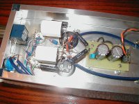
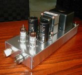
Brett, I think all of your advertising has worked, because here’s another 12B4A preamp.
I just finished it a couple of days ago but have a problem, maybe one of you here can help me. I’m getting a random, very low frequency noise out of the preamp, and I can’t figure where it’s coming from. On a scope, with the SEC/DIV setting on 0.1s, it looks like the output is tracing the contours of a mountain range, very random and very jagged. The amplitude of the “mountains” are generally around 40mV peak, but I’ve seen them jump to around 120mV. The signal seems to randomly swing negatively or positively. Looking at the speakers moving around, the mountain shapes appear around twice every second or so.
I’ve also looked for the signal on the power supply, but this is hard to do. I’m not sure how far I’m allowed to move to the vertical position around, so I used the scope AC coupled, and it seems that the signal also exists on the power supply. This problem exists equally on both channels, and does not seem to interfere with music signals played thru it. Not that I know this for sure, but the preamp sounds pretty good.
I originally had no film bypasses in the amp, but because of rectifier induced noise, I added 0.047uF film caps to each 50uF cerafine. This completely solved the rectifier noise problem, but the sound turned very sterile; slow and even colder than Harry’s diamond buffer. This morning I replaced these with some 4.7uF Hitachi polypropylenes, and these seem to work quite well. I’m finally getting clean warm sound. None of the bypasses caused the least change on the low frequency noise however.
I’d keep listening to see how the sound changes as time passes, but I can hardly do so with the way the preamp is now. Any suggestions?
*edit: those are 100uF cerafines in the PS*
Attachments
Nice layout. Have you tried different tubes? I know that sounds kind of silly but I was having a 60hZ hum problem in my new amp until I biased the heaters above ground (as I see you did) and changed the driver tube. Viola! no more problem.
I'd be immediately suspicious of connections in the PS or maybe even leakage from a cap or a diode. Swap some caps around (like the 50s for the 33s) and see if the problem moves.
Just for my own personal learning experience, what did you see Sy? Or are you going by intuition? Learn me sumpin SY!!🙂 🙂
Well, it's correlated between the channels. That says, "Power supply!" You looked and, indeed, that's what it was. Now, what sorts of things can cause the power supply to jump around? There are lots of possibilities, but of the myriad I first look at the least reliable stuff- my own soldering work, then electrolytics, then diodes.
If you swap the 50s and 33s, BTW, either the problem will go away, will continue on both channels, or suddenly be confined to one channel. Each of these outcomes tells you something.
If you swap the 50s and 33s, BTW, either the problem will go away, will continue on both channels, or suddenly be confined to one channel. Each of these outcomes tells you something.
heater-cathode leakage?
I've heard that 12B4 are prone to heater-cathode leakage that can cause some strange noises, possibly low frequency. Nice preamp, by the way. I built a similar model myself and like it very much. I use a 20uF bypass on the heater voltage divider rather than the 0.22uF you show. I found that cut down on some hum noise.
As for the mountain range, both your speakers and your ears are better than mine if you can hear a 2Hz noise signal I have seen the same behavior on my scopes though, even on the output of actively regulated supplies. I actually think it might be a spurious signal coming out of the air. The pumping of your speakers is of course real, but I am not an expert on motorboating so I can't suggest a cure at the moment.
Michael
I've heard that 12B4 are prone to heater-cathode leakage that can cause some strange noises, possibly low frequency. Nice preamp, by the way. I built a similar model myself and like it very much. I use a 20uF bypass on the heater voltage divider rather than the 0.22uF you show. I found that cut down on some hum noise.
As for the mountain range, both your speakers and your ears are better than mine if you can hear a 2Hz noise signal
I have seen the same behavior on my scopes though, even on the output of actively regulated supplies. I actually think it might be a spurious signal coming out of the air. The pumping of your speakers is of course real, but I am not an expert on motorboating so I can't suggest a cure at the moment.Michael
One other thing to think about. On a 5842/417A there is more than one pin connected to the grid. The same goes for the 12B4A. Try soldering a 220 ohm resistor to pin 2 and another to pin 7 and solder the signal wire to both of them. It might help.
As G has suggested the extra grid pin can and does cause problems when left alone.
I am fortunate enough to have Michael as a friend of only a short driving distance away. I to had a hum problem and followed his advice to the letter and obtained a hum free 12B4 line stage.
I see you are running 37 volts to to the heaters off the main supply. I used a variable resistance and settled on 50V to ward off the nasty 60 cycle hum.
In all I personally think the 12B4 is a very nice line stage. I scrapped my 5687 line stage after hearing Michaels 12B4 and used its chassis for the 12B4 unit I built.
In all a VERY nice job on construction and layout.
Joe
Hi Greyhorse,
I was wondering if you would be so kind as to tell me where you obtained the James power transformer? I would like to find a reliable source for them. Is there one in Ontario?
I was wondering if you would be so kind as to tell me where you obtained the James power transformer? I would like to find a reliable source for them. Is there one in Ontario?
Thanks for all the replies, and sorry I took so long getting back to you guys, but I spent all morning re-building a chip-amp to burn-in my newly completed FE207E bass reflexes. With summer here, I desperately needed an amplifier more efficient than the Aleph Mini I’ve been using before.
Getting back on topic, I said in my first post that it was hard to tell, but there probably was noise in the power supply as well as on the preamp outputs. It was hard because used AC coupled, the ‘scope filtered out most of the noise. Using a 1uF 400V cap I happened to have lying around, along with a 1M resistor, I was able to take a proper look at the power supply, and –yes- the noise definitely exists on the power supply.
Next step, I went and isolated the PS and the amplifier. I replaced the vacuum tubes with 2, 4.12K resistors I made with a bunch of spare parts (ah, the convenience of having so many unfinished/failed projects around), to closely duplicate the current drawn by the tubes. Although the waveform of the noise was less jagged (no noise from the heaters?), the amplitude of the “mountains” I was referring to earlier, didn’t change.
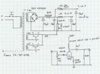
So what now? Because the noise is a mirror image across both channels, I think it’s safe to say the 100uF cerafines aren’t to blame. That leaves the 2, 33uF Nichicon PWs D-K started carrying, and the IXYS soft recovery diodes. Fairly high performance parts, both, but I guess this doesn’t have anything to do with their likelihood of being defective… Darnit, now I’m going to have to start desoldering stuff. I guess there’s no other way to troubleshoot this preamp right?
This being my first vacuum tube attempt, one thing I learned so far is that I need a lot more spare large value resistors and high voltage capacitors in my parts bin. I think I used every spare film capacitor with a voltage rating above 400V to build/test this preamp.
Also thank you to all of you who wrote positive comments about my layout. I always liked the way the older Cary stuff was laid out, and decided to copy their thin/deep chassis design. One problem with this layout is the lack of space to add stuff more features though. No CCSs or battery biasing for me I think.
Gavin, the James transformer was something I picked up while living in Japan, from Hino Audio in Akihabara. I hope you have luck finding them from those alternate sources in that other thread.
Getting back on topic, I said in my first post that it was hard to tell, but there probably was noise in the power supply as well as on the preamp outputs. It was hard because used AC coupled, the ‘scope filtered out most of the noise. Using a 1uF 400V cap I happened to have lying around, along with a 1M resistor, I was able to take a proper look at the power supply, and –yes- the noise definitely exists on the power supply.
Next step, I went and isolated the PS and the amplifier. I replaced the vacuum tubes with 2, 4.12K resistors I made with a bunch of spare parts (ah, the convenience of having so many unfinished/failed projects around), to closely duplicate the current drawn by the tubes. Although the waveform of the noise was less jagged (no noise from the heaters?), the amplitude of the “mountains” I was referring to earlier, didn’t change.
So what now? Because the noise is a mirror image across both channels, I think it’s safe to say the 100uF cerafines aren’t to blame. That leaves the 2, 33uF Nichicon PWs D-K started carrying, and the IXYS soft recovery diodes. Fairly high performance parts, both, but I guess this doesn’t have anything to do with their likelihood of being defective… Darnit, now I’m going to have to start desoldering stuff. I guess there’s no other way to troubleshoot this preamp right?
This being my first vacuum tube attempt, one thing I learned so far is that I need a lot more spare large value resistors and high voltage capacitors in my parts bin. I think I used every spare film capacitor with a voltage rating above 400V to build/test this preamp.
Also thank you to all of you who wrote positive comments about my layout. I always liked the way the older Cary stuff was laid out, and decided to copy their thin/deep chassis design. One problem with this layout is the lack of space to add stuff more features though. No CCSs or battery biasing for me I think.
Gavin, the James transformer was something I picked up while living in Japan, from Hino Audio in Akihabara. I hope you have luck finding them from those alternate sources in that other thread.
check scope
Before tearing apart your nice construction test your scope a bit. First, AC coupling in my Tek scopes merely involves putting a capacitor in series with the probe, just as you describe doing. If you have another power supply of somewhat similar voltage put your scope to that and see if the mountains are there. As I mentioned before, I have seen this sort of phenomena several times myself and it had nothing to do with the device under test. I think it was a bad powerline day or something because on those same days I would get much larger spikes when the refrigerator kicked on as well. No guarantees but it is usually a good thing to think about the possibilities for a bit before mucking around in a nicely laid out circuit.
Michael
Hi,
But if you must tear it to pieces:
Cheers,😉
P.S. Check for mistakes, I didn't redo any math on it.
Before tearing apart your nice construction test your scope a bit.
But if you must tear it to pieces:
Cheers,😉
P.S. Check for mistakes, I didn't redo any math on it.
Attachments
Hi!
Just a thought; Maybe the tubes are picking up mechanical vibrations from the chassis... I have had som problems with this, and it was solved with either a pair of new tubes or isolating the tube sockets (or Output caps!!!) from vibrations.
Also, this might remind me of a weak motorboating....
You might try to make a centertap for the heaterwindings with 2 resistors in series, and refering the midpoint to the elevated voltage...
And perhaps you can try putting both the 100uF caps in paralell AFTER the 220R resistor in the PSU. The 220R will be in series with the choke and damp the slight resonance peak of the LC filter....
stigla
Hi,
Stigla,
I'm the one guilty of putting that 220R resistor in and shifting the PS caps around...
Cheers,😉
Stigla,
And perhaps you can try putting both the 100uF caps in paralell AFTER the 220R resistor in the PSU.
I'm the one guilty of putting that 220R resistor in and shifting the PS caps around...
Cheers,😉
Motorboating? Probably not- this is a single stage, so there's not much opportunity for positive feedback through the supply rail.
The construction is indeed quite pretty, much nicer than the duct-tape and superglue messes that I assemble.
The construction is indeed quite pretty, much nicer than the duct-tape and superglue messes that I assemble.
Because the noise occurs in the power supply with the tubes removed from circuit, I know it has nothing to do with heater-induced noise or instability that might be solved with grid-stoppers.
Stigla, you mentioned there might be resonances between the inductor and capacitors, and that was my thought too. Where is the best place to place this series resistor? Between the inductor and the second 33uF capacitor? Also what is the minimum value that could be used and still be useful? Thanks in advance.
Stigla, you mentioned there might be resonances between the inductor and capacitors, and that was my thought too. Where is the best place to place this series resistor? Between the inductor and the second 33uF capacitor? Also what is the minimum value that could be used and still be useful? Thanks in advance.
Hi,
That was my thought as well which is why I took the liberty of redrawing the circuit.
With equal cap values infront and behind the choke chances are it resonates.
If you care for sims:
DUNCAN AMPS.
Cheers,😉
Stigla, you mentioned there might be resonances between the inductor and capacitors, and that was my thought too
That was my thought as well which is why I took the liberty of redrawing the circuit.
With equal cap values infront and behind the choke chances are it resonates.
If you care for sims:
DUNCAN AMPS.
Cheers,😉
- Status
- Not open for further replies.
- Home
- Amplifiers
- Tubes / Valves
- Low frequency noise in a 12B4 preamp