Hi
I create uc3825 based half bridge smps (pulse transformer gate driving, 30khz, max duty cycle %47).
My first test voltage 16v and irfz44 mosfets.
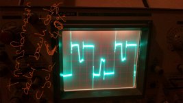
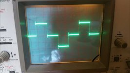
Low cycle wave problem
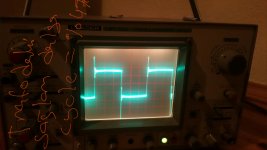
Max cycle wave not problem
(Power transformer out wave)
Bad english sory
I create uc3825 based half bridge smps (pulse transformer gate driving, 30khz, max duty cycle %47).
My first test voltage 16v and irfz44 mosfets.
Low cycle wave problem
Max cycle wave not problem
(Power transformer out wave)
Bad english sory
Attachments
Last edited:
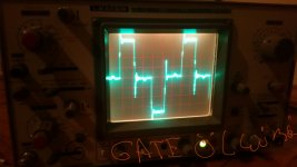
Pulse transformer outputs not connected mosfet gates
Attachments
Last edited:
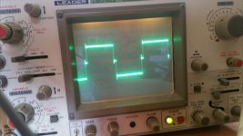
You don't actually have a problem: your waveforms are normal for a no-load condition.
I'll try to explain:
Let's start at the instant 2.5 horizontal divisions: the high-side MOS begins to conduct and pulls the output towards the + rail.
At the instant 4H, the conduction stops, and the current in the magnetizing inductance of the transformer continues to flow, pulling the output to the - rail, where it is clamped because of the body diode of the MOS.
At the instant 5H, all the energy stored in the transformer has been returned to the supply, and the transformer returns to a quiescent condition, I=0, V=0, meaning the voltage returns to the mid-supply, until the next half-cycle starts at 5.5H, in the opposite direction
- Status
- Not open for further replies.
