From the above measurement it shows that the first dipole dip is about 2.3dB at 1.2kHz.
If your tweeter can not be crossed that low then I would expect the dip is audible, which can impose a small amount of colouration to the sound, given that our ears are highly sensitive between 1kHz - 4kHz.
The baffle needs to be narrowed down (nearly halved) to push this dipole dip to about 2kHz, so that it can be dealt with with the crossover. From my memory, the NaO has a baffle width of 28cm and the first dipole dip is around 2kHz.
However, in that case, the first dipole peak is much higher, and you can expect the dipole rolloff comes in much early. The P13 (it is a 5" from my memory) can easily run out of excursion and I am not sure if you can cross it anywhere lower than 300Hz-350Hz for a reasonable sound pressure capability.
That is why the Orion uses a 8" woofer and the NaO uses twin 6"5 woofers in a MTM. The larger cone area is needed for the dipole rolloff. The larger drivers are also more directive at higher frequencies, therefore reducing the dip at 2kHz. They are low-passed at about 120Hz - 150Hz.
If the P13 is crossed over above 300Hz, the woofers may not work in a H-frame or U-frame because of the 1/4 resonance. The resonance for a sealed box is twice higher at 1/2 wavelength instead of 1/4. But in practice, I have my U-frame heavily damped and I could not detect any resonances. I am crossing my woofers at 175Hz and it seems the bass is very clean.
Just a thought with regards to your baffle width.
I have had this idea for a long time but have not had an opportunity to try it.
How about adding sound absorbing materials on your baffle? For example, wool batts / blankets or even open ceil foam, attaching them on both sides of the panel just about an inch away from the driver edge and extending right beyond the baffle edge for up to 2 inches. Note that sound absorbing is only effective when the sound absorbing materials are as thick as about 1/4th of a wave length. So for a 1kHz signal, the sound needs to travel 34cm / 4 = 8cm through the damping material in order for the sound to be sufficiently damped.
Such damping should almost completely eliminate the dipole dip, allowing you to keep your existing wide baffle and use the small P13 to do the work without suffering the loss of efficiency. One headache I have with dipole speakers are the severe diffraction effects, which also seems to be visible from your measurements. Using the above method can possibly eliminate the diffraction effects.
As for asthetics, I was thinking about getting a upholsterer to make something to wrap around the damping material / speaker panel, with nice looking fabric. It can be made to look stunning.
Regards,
Bill
S7
Sorry to not updating as I have been very lazy and the weather was so nice yesterday 😎
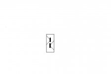
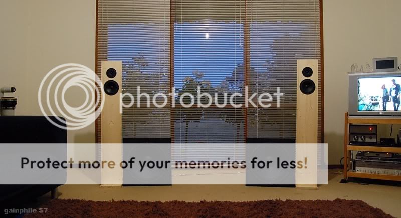
I solved the problem by redesigning the baffle. P13 and tweeter mounted on small, tall baffle and the woofers are separate. It looks really pretty to my surprise, no more huge monolith.

Most importantly, I did outside measurement and they reflect the theoretical dipole models. Off-axis response is smooth. The pic below is raw, unequalised response (valid above 200Hz or so). The notch is very easily implemented.

How good does it sound? Well, I've packed up even before my usual "let's hear them for a week" . Either this is my "last speaker" or maybe the curse of OB gods will haunt me to $pend and build an Orion.
I'll try to post a picture soon.
Sorry to not updating as I have been very lazy and the weather was so nice yesterday 😎
I solved the problem by redesigning the baffle. P13 and tweeter mounted on small, tall baffle and the woofers are separate. It looks really pretty to my surprise, no more huge monolith.
Most importantly, I did outside measurement and they reflect the theoretical dipole models. Off-axis response is smooth. The pic below is raw, unequalised response (valid above 200Hz or so). The notch is very easily implemented.
How good does it sound? Well, I've packed up even before my usual "let's hear them for a week"
. Either this is my "last speaker" or maybe the curse of OB gods will haunt me to $pend and build an Orion.I'll try to post a picture soon.
Just yesterday I thought of this fellow, all drivers the same
Could be the one of new underhung TB 4"
It wasnt thought as a dipole, but I suppose it would work nicely as dipole too, maybe with some kind of woofer module
Crossover is a quite simle 2.5way...which means 6 drivers in all will play midbass, and ought to result in low distortion 😀
One driver is solely "tweeter", crossed somewhere lowish 😎
Attachments
gainphile,
from your drawing it looks like your tweeter now is almost equidistant from the top and the sides of the baffle. If that´s the case: Is it intentional or by chance? In the first case you need to equalise a dipole peak for the tweeter too. In second case I would recommend to cut the baffle just above the tweeter to make the edge radius around the tweeter as "divergent"(?) as possible. Perhaps you should simulate it in EDGE.
from your drawing it looks like your tweeter now is almost equidistant from the top and the sides of the baffle. If that´s the case: Is it intentional or by chance? In the first case you need to equalise a dipole peak for the tweeter too. In second case I would recommend to cut the baffle just above the tweeter to make the edge radius around the tweeter as "divergent"(?) as possible. Perhaps you should simulate it in EDGE.
Product shot... finally 😀
Rudolph, that's a great insight. I honestly did not simulate the tweeters as this one uses a low-end one, I have not decided on what tweeters to be used. In saying that I have no complaint about high-end smoothness and extension.
Tinitus,
Yes as soon as I mounted the mid and tweeter on that skinny baffle with pretty pine grain, the immediate thought was... wow these have great WAF I wonder if 4 or 5 small woofers will do. We'll save that for S8 okay ? 😉
Finally my insights to this point:
1. The difficult part of OB is not bass (surprisingly) but midrange. OB midrange will have peaks which needs to be corrected. Midrange should use the lower part of dipole peak, not the upper part where freq. response is not smooth, although low-freq. rolloff is avoided.
2. Big baffles to extend low-end frequency just doesn't cut it for the midrange. It will suffer.
3. OB can be simulated using good software such as John's ABC Dipole program. I know that SL thinks otherwise.
Those look really great, gainphile. 
I would rate their WAF much higher than the Plutos in the back. And I fully support insights 1-3. Although I don´t see, why SL would oppose Nr. 3 more than JohnK would.
If those woofers would be in a shallow H frame (total depth 20 cm), giving them a little bit more depth/volume, the nice aesthetic balance between mid-high slenderness and down-to-earth bass could be even more convincing IMHO.
Did I say I really like that combination? 😀
would it be possible to hide the woffers perpendicular on the back of the baffles? would it still sound right? you probabily can give it a fast try... pardon me if it is a dummy question...
and the second dummy question is...
is the tweeter working dipole this way? or should you be considering to add a another on the back, like in the orion++?
is the tweeter working dipole this way? or should you be considering to add a another on the back, like in the orion++?
Rudolf,
Thanks for the complements. I too, having done few OBS with little regard on aesthetics was quite surprised with their pleasing effect. I know it just looks but it does count apparently. No wonder the wife frowned upon my huge twin-1.2m baffles before 😀
Human,
I tried that actually, putting the "subs" behind midrange panel. But it does not sound right. Probably 1) some spectrum of sound was blocked, 2) driver offset requires different delay correction circuit, or 3) both. Anyway I went to the path of least resistance there.
I use rear tweeters which fires inverted phase (like NaO and Orion+).
Strange but my perception is the opposite, very easy to get good even excellent mid-range OB much harder to get acceptable bass. This may be just my aging ears.
One thing about your compound baffle is thae high WAF, being black the woofers are not as apparent as the tall blonde towers of the mid-range optical illusion, also you have effectively give tha extra width to the bass baffle increasing the bass and asymmetric as well.
Nice job
One thing about your compound baffle is thae high WAF, being black the woofers are not as apparent as the tall blonde towers of the mid-range optical illusion, also you have effectively give tha extra width to the bass baffle increasing the bass and asymmetric as well.
Nice job
To be clear: it's easy to get OB bass response using *active* xo. I can imagine the difficulties of doing this when passive.
With active, many types of circuits are at disposal: shelving lowpass, compound shelving lowpass, linkwitz transform etc.
In hindsight, the midrange panel of that S7 could have been easily built using passive. This would be similiar to NaO approach, "hybrid". But in these days a good coil is more expensive than pair of gainclones 😀
gianphile, i'm trying to figure out how to project an openbaffle design for a pair of AN 8" fullrangers... i would like to have the baffle to be as narrow as possible and then mount the woofer (mono sub or stereo dipole) separately, i need some aid thought with the electronics involved and the cutoff frequency the narroe baffle will push me to...
if you fell this being OT, please find the time to give me a mail
if you fell this being OT, please find the time to give me a mail
No problems 🙂
Let us know the Sd, Qts, and Fs of your driver. Let's see what's JohnK's simulator recommends of baffle width.
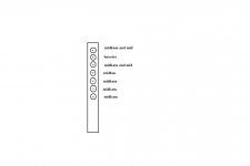
The electronics is not too difficult, use breadboard for prototyping. It would be something like this I think:
Buffer --> SLP --> XO HP --> Dipole Notch --> Delay correction --> FR 8"
........................--> XO LP --> Woofer/sub
Let us know the Sd, Qts, and Fs of your driver. Let's see what's JohnK's simulator recommends of baffle width.
The electronics is not too difficult, use breadboard for prototyping. It would be something like this I think:
Buffer --> SLP --> XO HP --> Dipole Notch --> Delay correction --> FR 8"
........................--> XO LP --> Woofer/sub
my drivers are audionirvana super 8", those are fullrangers unit on the budget (someway lowther inspired). the facts perhaps is that everybody is putting fullrangers on quite wide baffles togheter with the woofer or double woofer.
you seem to be the only one that went for a narrow baffle. which i found very nice, and also would maybe permit me to initialy buy just one woofer, and then adding a second one in the time...
at first i tought of an active sub, i'm afraid i'll get no punch and no body from a single woofer per chanel, but also i don't know wheter a sub could cover the midrange... looking for opinions...
for sure i would like the FR units openbaffle, on a narrow one.
gainphile said:
Let us know the Sd, Qts, and Fs of your driver. Let's see what's JohnK's simulator recommends of baffle width.
Fs = 37.462
Qts = 0.215
equivalent diagrham radius = 88mm
xmax is 1mm one way
i don't have a ready Sd parameter on the sheet... i'll be looking out how to calculate
thank you 🙂
I found Sd for that driver is 206cm2. With all this info JohnK's simulator shows good response with 110x25cm baffle, with driver mounted at 85cm. The placement of the driver seems to be critical. If I change that to 90cm, there is large dip around 1kHz region. Simulation picture is here but I really suggest to buy that $15 simulator, as it lets you play around before even cutting anything 🙂. No I'm not affiliated with JohnK except the common hatred of anything box 😀
The biggest hurdle will be to determine at what freq. Q, and depth the dipole peak would be and I had less luck with the simulator. I would simply mount the driver to baffle and run fullrange. Then add SLP 30 - 450Hz. Listen (at low volume!). If you have measurement tools dipole peak is quite measurable.
Nice driver btw. 🙂
so i need the woofers to go all the way up to 450 and then roll off.
do you think they will integrate smoothly at this frequency not being on the same panel? is the cut frequency so high also on your OB? would a mono woofer being in the middle work for a starting project, something more like a mono sub?
by mean of what electronic should this be done? see i really i'm a newbie, need some sort of step by step helping, hoped to find it here... also think a step by step guide to go OB is seek by many.
for example, going reverse:
having them bi-amped, t-class on the FR, and gainclone on the woofers, 25w/ch/8ohm for the woofer can work? (should i care for something special on the amplification side or can i go with a cheap gainclone kit from ebay?)
then i think there is the crossover wich i really don't know where to start looking to understand...
and then a pre-amp or something to have the overall volume under control?
can i use your mail for the stupid questions?
unfortunately seem MJK has restricted the access to his software
human.bin said:so i need the woofers to go all the way up to 450 and then roll off.
do you think they will integrate smoothly at this frequency not being on the same panel? is the cut frequency so high also on your OB?
A major height difference and a suitable cross over frequency can work for you. There is a nice tool to test both different vertical driver distance and XO frequency:
An externally hosted image should be here but it was not working when we last tested it.
I reckoned the distance (center-center) as 60 cm and assumed a phase difference of 0°. The result: At the x-over frequency you will get nice SPL dips in the direction of floor and ceiling reflection. Not bad to have that.
It´s easy to play with XDir and look what happens. 🙂
- Status
- Not open for further replies.
- Home
- Loudspeakers
- Multi-Way
- Low-distortion OB