steenoe said:Nico, you are indeed lucky😉 Any chance to see some pictures of your amp? Sounds like an interesting project.
Steen🙂
agree with steen.........
btw steen-there is another stage candidate for susy(fying) 😉
Hi Steen,
I will publish pictures when it has been completed as well as give credit to those who contributed. I sincerely hope that it turns out to be as handsome as some of Nelson Pass' products. I don't care what anyone says looks count a lot!
It is nice to have a rich girlfriend, but it is much nicer to have a rich beautiful girlfriend.
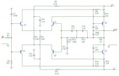
The amplifier is absolutely simplistic in design and inspired by Dan Augustina's original Krell KSA50, with some interesting variations utilising a microprocessor here and there. You may agree that it would be rediculous having a 200 watt per channel class A amplifier if the average listening level is only a few watts so quickly shifting the bias was a good option.
Our company developed patented predictive algorithms for our Anti Lock Brake systems that has been adapted for adjusting operating parameters quickly.
Please note that this is not a commercial development, I pay for everything even if I part own the company - nothing in life comes free- I am a team member and in the same league as anyone else working here and earn a salary.
BTW, I am not lucky, it took 35 years of hard work and a bunch of equally dedicated and loyal partners, employees, spouses and children, but persistance pays off eventually.
Don't be fooled, we are probably an insignificantly small company by American or European standards.
Kind regards
Nico
I will publish pictures when it has been completed as well as give credit to those who contributed. I sincerely hope that it turns out to be as handsome as some of Nelson Pass' products. I don't care what anyone says looks count a lot!
It is nice to have a rich girlfriend, but it is much nicer to have a rich beautiful girlfriend.
The amplifier is absolutely simplistic in design and inspired by Dan Augustina's original Krell KSA50, with some interesting variations utilising a microprocessor here and there. You may agree that it would be rediculous having a 200 watt per channel class A amplifier if the average listening level is only a few watts so quickly shifting the bias was a good option.
Our company developed patented predictive algorithms for our Anti Lock Brake systems that has been adapted for adjusting operating parameters quickly.
Please note that this is not a commercial development, I pay for everything even if I part own the company - nothing in life comes free- I am a team member and in the same league as anyone else working here and earn a salary.
BTW, I am not lucky, it took 35 years of hard work and a bunch of equally dedicated and loyal partners, employees, spouses and children, but persistance pays off eventually.
Don't be fooled, we are probably an insignificantly small company by American or European standards.
Kind regards
Nico
The nicest of the two is to have a beautiful girlfriend😀 Who would like a rich and ugly one😀It is nice to have a rich girlfriend, but it is much nicer to have a rich beautiful girlfriend.
Yeah, I was pretty X'ed, when I first saw the schematic🙂 For what it is, I think Nico has a really appealing simple circuit here. I like it.btw steen-there is another stage candidate for susy(fying)
Regarding the luck, I know that no such thing excists. I am looking forward to see more from you Nico😎
Steen🙂
I used a similar topology, with different transistors, in replacing broadcast mixing console opamps in the late 80s early 90s. The power supply was much lower, typically +/- 15 as found in the consoles, but it was a very good improvement to the TLO71's and NE5534s that were in the them originally.
I used a complementary matched pair of input transistors, the numbers escape me at the moment. (might have been 2sa798/2sc1385, but I really don't know for sure, and the documents are packed away somewhere) I used 2n4403s for the outputs.
I noted that some extra compensation was necessary to make them absolutely stable, and found that using darlington connected outputs actually helped somewhat without messing up the sound.
I later went on to use complementary matched fets (2sk389/2sj109) that were cheap and plentiful back then, and I liked the results even better. You could make the circuit with the 2sk170/2sj74 units, but even these are becomming hard to source.
I dont think that a "DIY-hard"DIY'er cares much about the fact that certain parts are hard to get😀 If the Toshiba parts are easy enough to implement in this circuit, That would be great! Looking at the objectives of this preamp, I dont think those parts will survive though😉 The circuit might be great with them, but if you read the first post, one condition to be filled is running it from a poweramp voltage! Nonetheless, your suggestions are pretty interesting. Might even sound good, with the powerrails adjusted?I later went on to use complementary matched fets (2sk389/2sj109) that were cheap and plentiful back then, and I liked the results even better. You could make the circuit with the 2sk170/2sj74 units, but even these are becomming hard to source.
Steen🙂
BTW. the so-called matched j-fets 2SK389 and 2SJ109's are not all that matched. You can ditch about 50% of them for seriuos hifi circuits!
phono
Can you post this with the RIAA stage?
Id like to see how to make this into a phono stage, what is the gain?
Can you post this with the RIAA stage?
Id like to see how to make this into a phono stage, what is the gain?
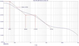
AH THE GAIN HE ASKS. THIS ONE AT THE VERY SPECIAL PRICE IS 40dB. Gain is normalised to that at 1kHz
This is a little bit of a farse how RIAA equalisation curve should look. A pick up has an output voltage related by the velocity. Most Pick-ups are essentially linear so I guess the Hi-Fi buffs from yonder years thought it great to emphasize the mid band where your ears work the best anyway.
Mid-band will thus sound as the boffs say airy, open, spacious and all the other descriptive crap they can dream of.
I in particular have a TIFF with these wordly audio reviewers, who half of the time don;t have a clue what they are talking about.
I personally could care a flying F&%K if you like what you hear keep it, else tweak it until you like it. Then permanently weld the case closed so that you don't fiddle with it ever again. If you leave access to the guts, you will eventually destroy it.
Once you like it no tweak will make it better only different from before, if you keep on tweaking eventually you will loose any point of reference you think you had.
I maintain build a project with the best components you can afford listen and like or dislike it, don't start messing with polupropelene sounding better that polycarbonate or silver mica, or plain old ceramic. in every cap there is a phase change and this is the main culprit of crap or good sounding equipment. Phase distortion causes the under and over-tones be shifted in relationship with their position in time with regard to the rest of their mates making up a particular note on a particular instrument.
My suggestion is remove all capacitors from any signal path - capacitors are only there to provide a lot of instant energy should you need it, they are not good for things other than delay timers, but has little other use in audio.
Attachments
steenoe said:I dont think that a "DIY-hard"DIY'er cares much about the fact that certain parts are hard to get😀 If the Toshiba parts are easy enough to implement in this circuit, That would be great! Looking at the objectives of this preamp, I dont think those parts will survive though😉 The circuit might be great with them, but if you read the first post, one condition to be filled is running it from a poweramp voltage! Nonetheless, your suggestions are pretty interesting. Might even sound good, with the powerrails adjusted?
Steen🙂
I understand about the high voltage rails; just adding my experience with that circuit topo with lower voltage rails. The Toshiba parts will work well with +/- 24 Volts. They sounded good even with the +/- 15 volt rails.
"BTW. the so-called matched j-fets 2SK389 and 2SJ109's are not all that matched. You can ditch about 50% of them for seriuos hifi circuits! "
I too found they were not always well matched, but matched well enough for this type of circuit. BTW, biasing with the FET input stage was accomplished {similarly to the John Curl JC-2 circuit, I think} with a fixed plus variable R in series between the junction of the N & P FET's sources. IIRC the drain R was about 2.0k for the +/- 15V rails with BL devices. Don't recall the other values. Still looking through boxes upon boxes after moving to a new house.

electrode10101 said:
II too found they were not always well matched, but matched well enough for this type of circuit. BTW, biasing with the FET input stage was accomplished {similarly to the John Curl JC-2 circuit, I think} with a fixed plus variable R in series between the junction of the N & P FET's sources. IIRC the drain R was about 2.0k for the +/- 15V rails with BL devices. Don't recall the other values. Still looking through boxes upon boxes after moving to a new house.
Is it by any chance possible that you cold post a schematic with this topology adapted for JFet input. Thanks
Looks nice and simple.
I too fowour the high volage rails. Once i heard a simple mosfet preamp driven at 300 V It sounded fantastic.(IV-converter for AD 1865).
Dear MiiB,
I must admit, never used JFET in my entire carreer, and it would be totally inapropraite if I attempted this. Maybe there are some of our other friends out there that would like to assist.
I have used small signal transistors at 35V previously with equal success (MPSA06/56), but when one needs to use it with moving coil cartridges noise is important abd the power transistors having physically bigger junctions generates less noise.
There is nothing magical about this topography, the fact that it is class A results in lower odd order harmonics and the high rial suppresses third order intermodulation products.
If you would like to use it at lower voltages, it is fine but resistor values need to change in order to keep it super linear.
Regards
Nico
steenoe said:Nico, you are indeed lucky😉 Any chance to see some pictures of your amp? Sounds like an interesting project.
Steen🙂
Dear Steen,
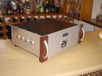
I was totally taken by the idea of 200 W class A only to realise that it can only be placed in the swimming pool. So I halved the output devices, threw out one of the 1 KVA transformers and turned the bias down running class AAB.
I think sometimes going overboard can be a very stupid wasteful thing!
Anyway the picture you requested.
Attachments
Nico Ras said:
Dear Steen,
I was totally taken by the idea of 200 W class A only to realise that it can only be placed in the swimming pool. So I halved the output devices, threw out one of the 1 KVA transformers and turned the bias down running class AAB.
I think sometimes going overboard can be a very stupid wasteful thing!
Anyway the picture you requested.
nice bottles

I use specially produce square Jack Daniels as output pair.Zen Mod said:
nice bottles

Nice work🙂 I am sure a good pour of Jack Daniels is in order to celebrate that fine looking amp🙂Anyway the picture you requested.
Steen😎
Hi Nico
I am planning to build a pre-amp for my Pass A40 power amp. Your design impressed me. Before I can go ahead to proceed with this pre-amp. I like to know what is the value of R1 & C2 (220P same as C3 I guess) on the line stage?
I am planning to build a pre-amp for my Pass A40 power amp. Your design impressed me. Before I can go ahead to proceed with this pre-amp. I like to know what is the value of R1 & C2 (220P same as C3 I guess) on the line stage?
Nico Ras said:in every cap there is a phase change and this is the main culprit of crap or good sounding equipment. Phase distortion causes the under and over-tones be shifted in relationship with their position in time with regard to the rest of their mates making up a particular note on a particular instrument.
A remarkably strong claim. Would you care to explain?
Phase shift in capacitors is only a problem near the rolloff point and it's easily cured:
1) Use a large or small enough cap that rolloff is pushed out of the audio range.
2) Make sure that the capacitance is driven by plenty of current.
Poof! Problem solved.
Grey
1) Use a large or small enough cap that rolloff is pushed out of the audio range.
2) Make sure that the capacitance is driven by plenty of current.
Poof! Problem solved.
Grey
analog_sa said:
A remarkably strong claim. Would you care to explain?
Pure physics.
GRollins said:Phase shift in capacitors is only a problem near the rolloff point and it's easily cured:
1) Use a large or small enough cap that rolloff is pushed out of the audio range.
2) Make sure that the capacitance is driven by plenty of current.
Poof! Problem solved.
Grey
Never had this problem because I don't use caps in audio path in any of my designs.
- Home
- Amplifiers
- Pass Labs
- Low Distortion High Dynamic Range Pre-amp