Hi Krivium
Hope I'm not taking up too much of your time.
Do I need to test the midrange tone control next to eliminate it's influence?
I also have midrange drivers I can hook up to the terminals to include an audible element in the testing.
Cliff
Hope I'm not taking up too much of your time.
Do I need to test the midrange tone control next to eliminate it's influence?
I also have midrange drivers I can hook up to the terminals to include an audible element in the testing.
Cliff
Yes see you tomorrow.
I will organise a serie of test you could do to check.
One thing I noticed.
The white wire connector which terminates onto the tweeter protector terminal didn't have an insulating boot on the end.
These terminals are very close to the metal strip which houses the protectors.
The white wire above has a tributary white wire which feeds the Mid range protector.
Shorting of the white wire on the metal strip may or may not have had an effect, but I've now taped it up??
I've given the Tweeter protector switch a third test by placing it in the path between a battery and a driver.
The driver popped as expected, so the protector switch is OK?
Hi T.
The midrange is the issue, but when I spotted the missing insulation on the wiring servicing the tweeter protector, and as the same wire also feeds the midrange protector I wanted to make eliminate any possible influence.
The white wire feeding the tweeter protector has a soldered offshoot which feeds the mid.
So I'm thinking, maybe it's the midrange tone control??
you could...i'm not there so i've no idea what state of disassembly things are in, are the the mid drivers hooked up?
i would check for continuity of the control with the meter on a low ohm's range.
i would check for continuity of the control with the meter on a low ohm's range.
Last edited:
All drivers are removed.
I have another 5" driver I can reconnect to the wiring belonging to the midrange.
The tone device (EVW-B5A) has three terminals with light blue, dark blue, and orange wires.
Orange goes to protector switch,
Dark blue goes to tweeter tne adjuster
Light blue goes to cuircut board
I have another 5" driver I can reconnect to the wiring belonging to the midrange.
The tone device (EVW-B5A) has three terminals with light blue, dark blue, and orange wires.
Orange goes to protector switch,
Dark blue goes to tweeter tne adjuster
Light blue goes to cuircut board
Hi,
I thought about the protector: you could test it using a battery cell as the protector is nothing more than a switch ( which change state if there is more than 1,6amp present): you connect a wire from cell to a leg of protector, another wire from the other leg to the other pole of battery, and you check if dc is present or not ( probes at protector legs).
The Lpad ( levels) are located between filter output and driver and they are isolated from each others.
Edit: haven't read all and see you already did the battery test.
Cliff do you know how to read a schematic?
No concern about time, my pleasure if i can help. That said today i've got kids so i'll have less spare time.
Last edited:
Thanks Krivium.
I've had family issues here as well.
Sadly for tonight it's sandman time.
Perhaps tomorrow.
I have the schematic printed out.
I think I need to test the pot which adjusts the tone on the Midrange next.
I've had family issues here as well.
Sadly for tonight it's sandman time.
Perhaps tomorrow.
I have the schematic printed out.
I think I need to test the pot which adjusts the tone on the Midrange next.
Hi,
Cliff do you know how to read a schematic?
.
Hi Krivium
I have the schematic, but just a little rusty on understanding it fully.
It's made more difficult due to the absence of color coding (cables) .
But I think we're pretty close.
Midrange Driver tests OK (pops with battery)
Protector Switch tests OK (ohm test, and fitted into a driver circuit with battery).
Just need to test the Attenuator (EVW-B5A 8 Ohm 7807).
It has three cables running to its terminals.
Blue wire (common with the Tweeter attenuator)
Orange wire (goes to circuit board)
Light Blue wire (goes to circuit board)
Which attenutator terminals will I test and with which value?
Also, if the attenuator is cactus, do I just connect its wiring to by pass it?
If I did, would that equal the "normal" position on the attenuator (it ranges from 0 to 10 with "normal" between 8 & 9)?
NB: Is an attenuator a variable resistor?
cheers
C
Last edited:
yes the attenuator is a variable resistor, there should be low ohms continuity between all three terminals and you should see a variation in resistance between either outside terminal to the center pin when the shaft is turned.
what do you get across the the two outside terminals?
what do you get across the the two outside terminals?
Last edited:
Thanks turk.
Across the two outside terminals using Ohms 200 on the meter, I get:
7.2 Ohms at 0 on the attenuator dial
23 Ohms at 6.5 on the attenuator dial
Off the scale at 10 on the attenuator dial
Across the two outside terminals using Ohms 200 on the meter, I get:
7.2 Ohms at 0 on the attenuator dial
23 Ohms at 6.5 on the attenuator dial
Off the scale at 10 on the attenuator dial
sound like it's going open at the extreme end of the range?
is there a loudspeaker hooked up to the leads?
i'd try some contact cleaner.
is there a loudspeaker hooked up to the leads?
i'd try some contact cleaner.
Sorry for butting in, but I'd like to add to what turk 182 has said.
The schematic shows that the attenuator is a variable L pad control, and this is how I would check to see if it is OK.
Connect your ohmmeter probes between the centre terminal and one of the outside terminals, then slowly rotate the control.
Repeat between the centre terminal and the other outer terminal.
Depending on which outer terminal is connected, the reading should vary either between 8 ohm and 0 ohm or between 0 ohm and a relatively high value (say 50 ohm), and then infinity at full rotation.
N.B. You should remove the three wires from the L pad terminals before testing it..
Blue wire goes to terminal 1.Also, if the attenuator is cactus, do I just connect its wiring to by pass it?
Orange wire goes to terminal 3
Sky blue wire goes to terminal 2 (the centre terminal)
To bypass the L pad control, you would:
- Disconnect the blue wire from terminal 1 (and insulate its bare end).
- Leave the orange and sky blue wires in place, but connect a jumper (shorting) wire between terminal 3 and terminal 2.
Hi Krivium
I have the schematic, but just a little rusty on understanding it fully.
It's made more difficult due to the absence of color coding (cables) .
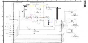
Ok, then the schem linked should help, it's very rough but should help (i am a great paint artist). 😉
What is inside the dashed line is on pcb, what is outside is located... outside it! For white i used black around the wires.
C3 (in purple) is the capacitor which could be the culprit IF this is not Lpad or Breaker. If it is not then L2 (0.39mH) could be the last component responsible but i dont see how it could break open.
I think you are close yes.
It could be a last thing though: a cold solder joint. But if it was the case the issue should have been already noticed before i think.
Attachments
Last edited:
About the Lpad you could use cleaner as Turk said.
I must say however i don't like that as i already killed some P&G faders with this kind of things. That said this was a different case and i don't think the same techhnology is used in these Lpad so why not try if it can bring them back to life?
On my own Technics the Lpad were definitely dead (they were stuck in place and i was never able to got them move again/back to life).
I hope it'll different for you.
Anyway if this happen you just bypass them or if your friend want them absolutely you can order some new.
They may not fit in place but as you planned to change the capacitors with new polyfilms you'll probably have to make a new external filter board as they wont fit in the original one (it is 'sandwiched' to the case and there is virtually no place for anything in the original case iirc): in this case you just make a box and place them in (and keep the original in place for look).
It's lucky to have individual input on yours (mine doesn't and i had to redo a polycarbonate plate for connectors i changed for speakons anyway).
Last edited:
- Home
- Loudspeakers
- Multi-Way
- Loudspeakers, no sound from left Midrange?