NTE7110 price
Paulb....yep I know, problem was with shipping cost to Australia and minimum charge for that. I did email Mouser to confirm costs. So for the two chips it worked out very expensive all up.
I have bought from Mouser several times and the saving on the items (vs buying locally) more than compensates for the shipping costs....but it depends on the items involved. At the time I did not need anything else from Mouser.
I did get an offer from a kind local to include them into his order for stuff from Mouser, but by that time I'd designed my own.
The way I have done it is close to line-ball wrt costs as the PIC also manages the Softstart. It is basically the NTE7100 vs a PIC and a few BC transistors. Add to that the fun and satisfaction of DIY and I'm am happier with what I ended up with.
Thanks for the tips muzza, I will work on improvements.
The parameter 1sec. for soft start I got from transformer manufacturer, I will double check if they got it wrong...
The parameter 1sec. for soft start I got from transformer manufacturer, I will double check if they got it wrong...
Here is the official site of the transformer manufacturer who says that softstart needs 0.5 to 1 second delay:
http://www.trafco.co.yu/softstart-en.php
http://www.trafco.co.yu/softstart-en.php
It's a replacement for the UPC1237, which you should be able to find online. I wired it according to the UPC1237 datasheet and it seems to work okay.d3imlay said:Is there an app not for the NTE chip. The PDF from Mouser only gives specs.
Not my intent to hijack the thread. Anyone wanting more details can email me.
Edit: Try http://www.ampslab.com/PDF/upc1237.pdf
paul
Muzza
I am looking for a softstart/speaker protection circuit to drive 4X500VA toroids that will supply power to 6 x GB300S psu's & onto 6 X GB300D SKA modules.
Your circuit appears to a novice like me to provide everything I need including soft switching but can it be adjusted via the ballast resistors to cope with the 2000va total of the toroids & can it handle switching 6 speaker dc detection relays.
If so would you be able to supply me with 2x pre-programmed PICT chips & pcb's if you have any left or can get more made.
I am in the UK but happy to pay any reasonable costs involved.
Your circuit is ideal due to the compact size & dimensions of the pcb.
Any help greatly appreciated.
Tim F
6 channels
Tim F, I'll assume all this is in one chassis.
Softstart:-
Only one of my PCBs should be required.
The current arrangement will handle 1 x 500A.
Installing 6 x 180ohm resistors to give 30 ohm ballast to handle 2 x 500VA trannies.
I have a Softstart Extender board which duplicates the RH end of the Protector PCB board which can be used to handle the second two 500VAs.
Speaker protection:-
I have developed a 2ch, 4ch and 6ch DC Detect Expander board.
The protector PCB has an Alarm extension header into which the Expander board can be plugged. So it can monitor 2, 4, 6 or 8 channels or more.
Multiple Relays:-
The Protector PCB onboard supply is 500mA so not probs there.
The relay drivers are BD681s which are an overkill wrt current handling (I tend to "over-engineer") but it means that the Protector PCB will handle the 3 speaker relays you need to use easily (assumes DPDT relays).
Of the power control relays, the mains one is straight across the supply so no issue.
The Softstart relay driver circuit is also BD681 so it will easily handle the Softsart extender PCB.
Oh, and another good thing is that the main on/off power switch on front panel will only be switching 50mA max.... the relays take care of the heavy switching 🙂
I have one Protector PCB left. I make the Extender boards myself as they are only single sided.
Let me know if that meets your needs.....
Hi Muzza,
are you able/willing to post or email your PIC coding and explain how you made the circuit connections into PIC?
are you able/willing to post or email your PIC coding and explain how you made the circuit connections into PIC?
Hi Muzza,
I've already received your extension pcb🙂 and they work well
Thank you very much....
BTW, Can i change 1N4001 with 1N4002?
Regards
Jopie
I've already received your extension pcb🙂 and they work well
Thank you very much....
BTW, Can i change 1N4001 with 1N4002?
Regards
Jopie
Yes Muzza all in one chassis, I hope!
So ONE combined soft start & protector board + ONE soft start extender board + ONE 6 channel d.c. detect expander board & if possible TWO pre programmed PICT chips would be great.
Just let me know figures & how you want to handle the transaction & we can go ahead?
By the way, does this redesigned board handles the a.c. detection from another source other than the front switch? It's not critical but would be usefull.
Thanks
Tim F
6 channel protector
Tim F, I'll email the details.
The power on/off is carried out by switcing on/off the small toroid on the Protector PCB. This, in turn, operates Relays to turn on the big toroids.
Does not matter how the small toroid is powered on/off.
In my setup, there are on/off switches on the power amps and these are on all the time. The power leads to the power amps are fed via the on/off switch on my Preamp (via IEC female socket on back of preamp)....so when I turn the preamp on the power amps turn on as well. The turn on current handled by the preamp on/off switch is not that large as full current is only carried by the switch contacts after they have closed (the 100mS softstart delay).... but then I am using two 300VA transformers so no issue.
In your situation, with your bunch of 500VA trannies, all that current passing through one switch would be a concern. You could add a 12v relay to be operated from the preamp and this relay switches mains to the Protector toroid. The actual mains feed would be directly connected to the wall.
Hi Muzza
That is all great news & will work for me fine.
Meant to ask the pcb sizes of the expander boards to allow me to work out the final stages of layout for my set up at this end.
Also transformer exact specs. so I can get that ordered up.
Look forward to mail with details shortly.
Thanks for your help & patience.
Tim F
Protector Soft Start performance
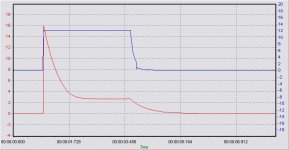
Guys, a little while ago I acquired a CRO adapter for my laptop. The unit has a storage function.
Over the weekend I built an AC current sense circuit to be able to see what was actually going on with the Soft Start part of the unit I built (did not have the CRO adapter when I first built the Protector unit).
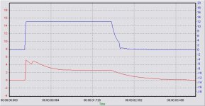
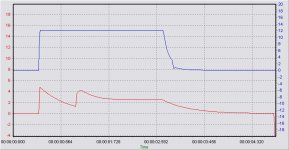
I tested with loaded and unloaded powersupply outputs plus I varied the Soft delay time at 100mS, 150mS, 250mS, 500mS, 750mS and 1000mS.
Attached are three of the traces I took when testing.
Connected were 2 x 500VA toroids and 23,500uF in each rail.
Each rail was also loaded with 100ohm resistors.
Note that the BLUE trace is the 12v supply on the protector and was included only to show On/Off state.
The RED trace is the mains supply current curve.
The rolloff of the red trace after power off is due to capacitance in my detector circuit...I did use as small a value as possible (680nF).
OUTCOME:-
Did lots of successive power on/offs and my 60ohm ballast via 3 x 180ohm 5W resistors handled the loads really well even at 1sec delays.
Looks, to me, like 100mS - 150mS is the optimum value for the Soft Start delay.
Confirms the reason why most other SoftStarts out there use 100mS or so.
The longer durations create a "double hump" effect which I would regard as undersireable....can probably be reduced by use of a smaller value resistor.... but cannot see any benefit in the second hump.
So.. I am sticking with the 100mS 🙂
Guys, a little while ago I acquired a CRO adapter for my laptop. The unit has a storage function.
Over the weekend I built an AC current sense circuit to be able to see what was actually going on with the Soft Start part of the unit I built (did not have the CRO adapter when I first built the Protector unit).
I tested with loaded and unloaded powersupply outputs plus I varied the Soft delay time at 100mS, 150mS, 250mS, 500mS, 750mS and 1000mS.
Attached are three of the traces I took when testing.
Connected were 2 x 500VA toroids and 23,500uF in each rail.
Each rail was also loaded with 100ohm resistors.
Note that the BLUE trace is the 12v supply on the protector and was included only to show On/Off state.
The RED trace is the mains supply current curve.
The rolloff of the red trace after power off is due to capacitance in my detector circuit...I did use as small a value as possible (680nF).
OUTCOME:-
Did lots of successive power on/offs and my 60ohm ballast via 3 x 180ohm 5W resistors handled the loads really well even at 1sec delays.
Looks, to me, like 100mS - 150mS is the optimum value for the Soft Start delay.
Confirms the reason why most other SoftStarts out there use 100mS or so.
The longer durations create a "double hump" effect which I would regard as undersireable....can probably be reduced by use of a smaller value resistor.... but cannot see any benefit in the second hump.
So.. I am sticking with the 100mS 🙂
Attachments
Hi,
the second hump is the increase in charge current to the smoothing caps when the ballast is removed allowing the transformer to send full voltage to the rectifier.
It will do no harm to either the transformer or the ballast.
If you want to give the rectifier or the smoothing caps an easier start in life then add a second delayed ballast to the secondary circuit. A Power Thermistor with relay bypass is suitable for this duty.
Alternatively, a gradually reducing ballast (Power Thermistor) in the primary will bring up the output voltage in a controlled manner rather than just a two stage step as with the resistor ballast.
What is quite clear is that the start up peak is indeed very short and those posters who said it takes just half a mains cycle (<=10mS) to establish the transformer flux were probably right. I had played (too) safe by recommending 300mS to 500mS for the start-up delay.
The second hump
AndrewT, thanks and yes I understood what the second hump was.
I was looking for a "smooth" powerup i.e. a situation where the current rises to a level and stays at that level (until music is applied)
This should achieve:-
1. Minimised current through the main fuse (no large spike),
2. Minimised switching current through the main relay contacts,
3. Minimal current across the soft start relay contacts at point of closure;
4. Achieve power supply stability faster.
IMO - This is what the goal of a softstart should be and the 100mS with 60ohm ballast achieves this.
The only real impact of the "second hump" is increased switching current across the soft start relay contacts. There is no value in having this current. In the 100mS/60ohm case the soft relay contact current is minimised.
Hope that clarifies.
- Status
- Not open for further replies.
- Home
- Amplifiers
- Solid State
- Loudspeaker Protector