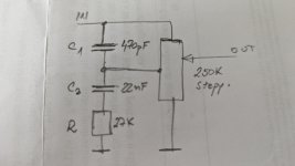
I add loudness circuit on stepped attenuator and my question is about quality of C1 capacitor. I think that C1 is in signal path and it's quality is important. My current C1 is ceramic type. Any suggestions which type of cap is best choice since value is only 470pF? I found Kemet paper, Silver Mica, caps, Wima MKP, Amtrans AMCH Polypropylene...
Thanks.
Thanks.
Attachments
All parts are "in the signal path".
Both series and shunt parts have equal effects on the audio signal.
But the type of part is a personal choice.
Of course, mylar or non-COG/NPO ceramics are bad choices.
Both series and shunt parts have equal effects on the audio signal.
But the type of part is a personal choice.
Of course, mylar or non-COG/NPO ceramics are bad choices.
Ceramic caps come in two sorts, one is C0G (also called NP0) and these are extremely good, linear as anything and stable.
The other sorts are extremely non-linear and to be avoided (X7R, X5R and similar types).
Buying C0G caps from a reputable supplier is the thing to do, disreputable sellers may sell X7R as C0G...
But a PP film type will also be absolutely fine.
The other sorts are extremely non-linear and to be avoided (X7R, X5R and similar types).
Buying C0G caps from a reputable supplier is the thing to do, disreputable sellers may sell X7R as C0G...
But a PP film type will also be absolutely fine.

There is no such thing as 'signal path'.I add loudness circuit on stepped attenuator and my question is about quality of C1 capacitor. I think that C1 is in signal path and it's quality is important. My current C1 is ceramic type. Any suggestions which type of cap is best choice since value is only 470pF? I found Kemet paper, Silver Mica, caps, Wima MKP, Amtrans AMCH Polypropylene...
Thanks.
http://lampizator.eu/HERESY/heresy.html
Signal flows to the ground.
Then its read by the next stage. Either by gate, base or grid.
What is in parallel to ground matters, that's all i wanted to pointed out. That coloured or dashed line in schematics of japanese service manual is not signal path. I read all the time 'lets put high quality caps in signal path and cheap stuff in parallel to signal. No such thing. Its the parallel parts which determine what's read by next stage.
Just putting shades on mona lisa mark?
In circuit analysis there is a method called "signal flow graph".
The flow is logical. End of story.
https://en.wikipedia.org/wiki/Signal-flow_graph
But have people have never heard of a voltage divider?
Shunt elements are not important, really?
The flow is logical. End of story.
https://en.wikipedia.org/wiki/Signal-flow_graph
But have people have never heard of a voltage divider?
Shunt elements are not important, really?
Oftentimes the signal is a voltage, not something that flows anywhere. The physical circuit sets up relationships between different parts of the signal path, ultimately there is a relationship between input signal and output signal. This relationship need not be purely one-way, as the above description suggests.Signal flows to the ground.
Then its read by the next stage. Either by gate, base or grid.
Just for the record, I have observed Mark’s contributions on circuit design many times on this forum and have found that these are well considered nuanced and complete and he is someone I would take advice from as he is rather better than I am in this area. Also he isn’t trying to sell me tube amps as the lampizator guys are. My advice would be to take that article with a large pinch of salt! It isn’t ALL false but needs to be read with a very critical filter IMO.
Before this spins off - better get back to loudness controls…
Before this spins off - better get back to loudness controls…
On the topic of loudness filter - I was looking at R.Slone's favorite preamp design from his Audiophile Project Sourcebook and I am struggling to understand how his loundness desing (below) is intended to work. With loudness 'IN' at volume turned down to zero the signal is not shorted to ground and the loudness network provides a voltage divider that gives already a significant signal for mids and further boosted for low and high frequencies. And indeed when I put it together and tested with line level input, it is not really usable without an additional pot between volume and opamp which will attenuate the signal. Could somebody explain if I am missing something? thx

Last edited:
There are pots with a 40% tap for loudness capacitors to go. If you have a stepped resistor pot a tap point may be available.
Your schematic should work. If the switch fails volume goes to max.
Your schematic should work. If the switch fails volume goes to max.
OK, I've doubled checked and the original design has a 4,7k resistor between volume pot and opamp (like below) but still at min volume it playes quite loud... I guess I should increase the value of that resistor to get a desirable level at low volume of this design?

Last edited:
Yes, I am aware of designs with center tap pots. Was just curious how this can be a recommended design.... and yes, I've used a loundess switch which turned out to have a zero center position and got some really nasty surprise when first switching loudness in/out 🙂There are pots with a 40% tap for loudness capacitors to go. If you have a stepped resistor pot a tap point may be available.
Your schematic should work. If the switch fails volume goes to max.
- Home
- Design & Build
- Electronic Design
- Loudness circuit on stepped attenuator