A seperate speaker disconnect relay, would solve your problems. About a one second delay before it switches inr
The simple circuit that I suggested in my earlier post #11 would come in handy.
If the two rails have very different capacitances now due to one of them deteriorating that would make any turn-on thump much worse as one rail rises much faster, so I'd definitely want to check the main filter caps. The arcing of the power switch happens long before the amplifier is able to respond to its EMI, so the switch can only be a source of noise at switch-off, not switch-on.
Its old enough for many capacitors to have deteriorated, so I suspect those first, after checking the bias settings (underbiased can produce instability)
It is now about 4 months since I started this thread. My move to a new home 700km from where I grew up. lived and worked all my life is complete. I quit my job, sold my condo and am now occupying the ground floor of a nice house far away from anything urban. Being as I am past retirement age, I have not sought employment yet so there is time to attend to the "projects" I brought along with me. Including this Sony TA-1150 integrated amplifier.
I should have reviewed this thread first because it seems I forgot the nature of it's problem. I had the notion the noise ocurred at turn off rather than turn on. My incorrect memory had me "google" that issue whereupon I learned of two diodes (D301 & D401) which prevent that from happening.
Surprisingly, I was able to get two new diodes in one of the nearby small cities and installed them. That was when I realized my error, noise was at power on not power off, and I re-read what I posted.
You mentioned insufficient bias and main filter caps.
I followed the service manual instructions re setting bias and it was off. Grosely so in one channel which was near zero. Both were re-set to 25mv but the turn on noise remains.
My attention is now on those filter caps but I do not have no means to test them. My only piece of equipment is a DMM. It does have a Capacitor Mode but it is useless with capacitors that large. Restricted as I am in that regard, would it be adviseable to obtain two new compatible filter caps from wherever and just replace them?
Hi
Before you go and make to many try and errors here a few things.
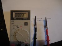
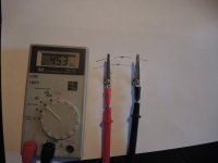
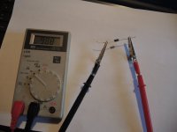
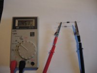
Diodes can be measured with a DMM, Switch to diode Sign and just hold the tips at both end on the diode.. 1 reading must be a number over 300. Reverse the testing pins of the DMM and this reading must be DEFINATELY HIGHER or open Cirquit.
You can measure this while in the circuits . Regular Diodes making seldom a short meaning 0.000 more than likely they will open like NC no reading on both sides.
If transistors are gone bad, then you would not get 25 /30,v DC at the output.
Make a picture form the Solder side of the Sony and also on from Top side.
Before you go and change capacitor and with this I mean the big ones, then first check out if you can cut the rails to the Output of the Amplifier..
If you see a way you can remove the AMP from Power-supply disconnecting who ever it is possible. Then using a 60 Watt Lightbulb and connect it across the Filter Capacitor in the Power Supply Secondary Side. Also connect the DMM to the Plus Minus of the Filter caps or the Bulb. Disconnect anything except the Power Cable.
Switch on and check the voltage across the Bulb, note it down and do the same thing for the Negative Voltage Rail. Both voltages must be same say +-0.1 Volts
Now to the actual Pop up Noise while powering on, if so, then I think honestly check out the DELAY circuit in the Amplifier if there is one..
In the meantime I try to find a circuit of the Sony and take a look at.. Do not buy Caps yet..
Before you go and make to many try and errors here a few things.
Diodes can be measured with a DMM, Switch to diode Sign and just hold the tips at both end on the diode.. 1 reading must be a number over 300. Reverse the testing pins of the DMM and this reading must be DEFINATELY HIGHER or open Cirquit.
You can measure this while in the circuits . Regular Diodes making seldom a short meaning 0.000 more than likely they will open like NC no reading on both sides.
If transistors are gone bad, then you would not get 25 /30,v DC at the output.
Make a picture form the Solder side of the Sony and also on from Top side.
Before you go and change capacitor and with this I mean the big ones, then first check out if you can cut the rails to the Output of the Amplifier..
If you see a way you can remove the AMP from Power-supply disconnecting who ever it is possible. Then using a 60 Watt Lightbulb and connect it across the Filter Capacitor in the Power Supply Secondary Side. Also connect the DMM to the Plus Minus of the Filter caps or the Bulb. Disconnect anything except the Power Cable.
Switch on and check the voltage across the Bulb, note it down and do the same thing for the Negative Voltage Rail. Both voltages must be same say +-0.1 Volts
Now to the actual Pop up Noise while powering on, if so, then I think honestly check out the DELAY circuit in the Amplifier if there is one..
In the meantime I try to find a circuit of the Sony and take a look at.. Do not buy Caps yet..
Attachments
Last edited:
The simple circuit that I suggested in my earlier post #11 would come in handy.
that is sure the best and most easy way. But, also it is necessary to find out why it pops...
I followed the service manual instructions re setting bias and it was off. Grosely so in one channel which was near zero. Both were re-set to 25mv but the turn on noise remains.
OK
I downloaded the service manual..
This noise actually can come from LINE DRIVE Stage as well.
What I saw it is easy to access the Filter Caps.. 4700uf/50Volts to check..
You can check them also with a DMM, but if you can get a ANALOQUE Volt - OHM - AMP Meter then you have better option to find out what's happen.. the reason is, because a Analogue meter measures faster then a DMM. you can use X1 Ohm and measure across the cap reverse when needle is up all the way, so you will be able to see the cap charge and discharge.
What you hear at the output is some kind of spike.. you can try to shut the inputs of the POWERAMP between Driver STAGE and POWER AMP to ground, this ensures that you don't get any noise in from Input side..
It's at the backside of the Housing and its called Power Amp In and it is connected with two iron bars from Output Preamp to input Power amp. this are RCA Connectors..
Take an RCA MALE Plug and lay center on to GND of the JACK. Insert it to POWER AMP INPUT>. this for both sides..
If the pre-section is the part wich creates noise, then it will be away,. if it still there then it the side of the Power amp.
Again connecting a ANALOGUE Voltmeter DC set to 1 VOLTS will show the spike on the Meter. The meter has to be connected to Speaker Terminals prior to switch on the AMP..
Any Questions just ask.. BTW I'm almost 70 too...
Last edited:
OK
I downloaded the service manual..
This noise actually can come from LINE DRIVE Stage as well.
What I saw it is easy to access the Filter Caps.. 4700uf/50Volts to check..
You can check them also with a DMM, but if you can get a ANALOQUE Volt - OHM - AMP Meter then you have better option to find out what's happen.. the reason is, because a Analogue meter measures faster then a DMM. you can use X1 Ohm and measure across the cap reverse when needle is up all the way, so you will be able to see the cap charge and discharge.
What you hear at the output is some kind of spike.. you can try to shut the inputs of the POWERAMP between Driver STAGE and POWER AMP to ground, this ensures that you don't get any noise in from Input side..
It's at the backside of the Housing and its called Power Amp In and it is connected with two iron bars from Output Preamp to input Power amp. this are RCA Connectors..
Take an RCA MALE Plug and lay center on to GND of the JACK. Insert it to POWER AMP INPUT>. this for both sides..
If the pre-section is the part wich creates noise, then it will be away,. if it still there then it the side of the Power amp.
Again connecting a ANALOGUE Voltmeter DC set to 1 VOLTS will show the spike on the Meter. The meter has to be connected to Speaker Terminals prior to switch on the AMP..
Any Questions just ask.. BTW I'm almost 70 too...
My thanks for taking the time to providing the explanation.
I do have a Micronta analog volt/ohm meter, just not immediatly at hand. Before I go searching for it, I believe you suggested determining if the noise is being produced before or within the power amp section?
This amplifier has a Normal / Separate switch on the back for disconnecting pre-amp and power amp. I just now tried turning the amp on with the switch in Separate position and no noise. Back in Normal position, the noise occurs. To me that suggests the noise is caused not within the power amplifier section but before.
And to whoever said "Youth is wasted on the young"....truer words were never spoken.
As an experiment this morning, I hooked the TA-1150's pre-amp outputs to an external power amp which has 12 segment LED power meters. I was wishing for a visual indication of how intense the TA-1150's noise transient was when it was switched on.
The burst was strong enough to light all 12 LED's momentarily and then the power amp's protection lamp lit for a second or two. FWIW that amp's LED meters have a calibration scale and the last segment is designated 400W.
Might there be any suggestions as to what component(s) within the TA-1150, but not in the power amp section, that could cause this burst?
Is the amplifier still running on original aluminium electrolytic capacitors?
Looks like an old amp. If it is from 1973 then they just need replacing, even the power supply capacitors.
That would be my first step to replace all capacitors, if I wanted to keep the amplifier. You may need to look at other parts for problems, but capacitors from 1973 will be past it and not helping.
My thanks for taking the time to providing the explanation.
I just now tried turning the amp on with the switch in Separate position and no noise. Back in Normal position, the noise occurs.
And to whoever said "Youth is wasted on the young"....truer words were never spoken.
Can you tell me is the POP on both sides or just on one side of the Loudspeaker.
For me this sounds like that the OUTPUT Section is ready to pass the sound before the Input has it's Play Mode reached.
Check if the the supply voltage on the input lacks behind the supply voltage of the power amp. if yes then I would check the filter Caps for the input stage, there are you just have to find them. You would need two voltmeters sitting just besides each other so you can see them both at the same time..Then power on and check which is up faster.. if the POWER AMP is up before the driver or input stage, check Protection resistors / these are very low Ohm usually so if something happen then these will open instead of burn.. I'm not on the computer I have the SCHEMATIC on so right now I can not take a look at if this Amp has protection resistors.. Old Amps up to 2000 most times had them. This will be something like 0.68Ohm or less may only 0.1ohm colors would be Brown Black Silver Gold this is for 0.1 and it would be Blue Grey Silver Gold for 0.68Ohm (I hope I got the color code right) Long time not used it.
Also remove all FUSES and CLEAN THEM or exchange with same new Fuses. Also clean the Holders of the FUSES.. I saw this so many time, that fuse holders where a part of the Problem. It doesn't need to be that way, but its always cheaper then new Components..
Your decision..
Last edited:
Since my last post, my attention was directed to some transistors involved in the mute circuit - Q501/502/503. According to the service manual, those arre 2SC634A's.
That was the transistor I found in position Q501 but it had black legs. A past encounter with simarly afflicted 2SC458's prompted me to replace it. I used a 2SC1815. That did nothing to correct the problem so I looked at Q502 & 503. Neither of those had the 2SC634A's which were supposed to be there and one of those I removed tested bad.
I have since replaced all three, Q501/502/503 with 2SC1845's. That has now caused the turn on noise to manifest on the left channel only but has somehow created minus 0.72V DC on the right channel pre-amp outputs.
My next task will be examining orientation of the three transistors I just replaced. I copied what was on the board but it was suggested that whoever preformed previous transistor replacement got it wrong.
Last edited:
It turned out that whoever worked on this amp in the past did put Q503 in backwards and I put in new transistors the same way.
The icons on the board were distorted so I can understand why someone could make that mistake. But I spotted the letter "E" next to one hole and realized it was in wrong.
Even though I only installed it yesterday, I pulled that transistor and put another new one in its place - correctly.
The problems I was experiencing with this amp seem to be gone now.
- Home
- Amplifiers
- Solid State
- Loud “snap” when turning on Sony TA-1150 integrated