I agree about elimination of ground loops but I ask about battery noise because, as you know, in digital the 1/f noise seems to be of particular importance when it comes to powering clocks. In-close flicker noise on the clock supply is purported to introduces jitter.
Batteries seem like a good option but without noise measurements it is really hopeful thinking (& how the music sounds). In this instance, it would be great to be able to correlate 1/f noise level Vs sound!
I have modded a HiFace unit by changing it's clock supply from an internal switching 3.3V regulator to a direct 3.3V battery feed & the jump in sound quality was amazing. It would be interesting to verify if this was as a result of lower 1/f noise/broadband noise/ground loop elimination.
I have modded a HiFace unit by changing it's clock supply from an internal switching 3.3V regulator to a direct 3.3V battery feed & the jump in sound quality was amazing.
That same result you'll see on the Squeezebox.
Cool, I'm looking forward to it but is it as a result of lower broadband noise, lower 1/f noise, elimination of ground loops, reduction of PS correlated jitter or some other factor or combination of factors?That same result you'll see on the Squeezebox.
-EC-,
That 1541 board looks so sexy! 😀
1/f noise 😱 ... it sounds like Bybee's could be mentioned...I better get off.
That 1541 board looks so sexy! 😀
1/f noise 😱 ... it sounds like Bybee's could be mentioned...I better get off.

John, I'm looking to create a balanced I2S feed to each of 2 DACs & I'm wondering how suitable the differential line drivers/receivers DS8921/22 are fro the job?. Would these be fast enough, low jitter? I know you've used them in your I2S synchronous re-clocker but this was for 16/44 - I'm looking at 24/192 signals.
Others have recommended using LVDS transmitters/receivers for low jitter & higher speed but can I use the differential output from a LVDS transmitter directly into the I2S input of a DAC?
What do you think is the best approach?
Pedja Rogic has published the I2S splitter shown which significantly differs from just inverting the data - is this a better way of doing the splitting?
Attachments
John, I'm looking to create a balanced I2S feed to each of 2 DACs & I'm wondering how suitable the differential line drivers/receivers DS8921/22 are fro the job?. Would these be fast enough, low jitter? I know you've used them in your I2S synchronous re-clocker but this was for 16/44 - I'm looking at 24/192 signals.
Others have recommended using LVDS transmitters/receivers for low jitter & higher speed but can I use the differential output from a LVDS transmitter directly into the I2S input of a DAC?
What do you think is the best approach?
Pedja Rogic has published the I2S splitter shown which significantly differs from just inverting the data - is this a better way of doing the splitting?
You never give up, don't you? How many threads do you have running around the www about your infinite number of problems and your infinite number of projects? Last hope seems to be John now. Good luck. 😉
sd player experience
hi klaus (soundcheck),
hope your are enjoying your new sd-player 🙂 . any report how does it sound with your hifi system and comparing to your existing dac(s)?
how did you connect your subs to it? low-level input or highlevel parallel to the speakers?
regards
mamal
hi klaus (soundcheck),
hope your are enjoying your new sd-player 🙂 . any report how does it sound with your hifi system and comparing to your existing dac(s)?
how did you connect your subs to it? low-level input or highlevel parallel to the speakers?
regards
mamal
Last edited:
Hi riotubes,
Output amplitude can be further increased using a clean external DC voltage. 10 K Ohm I/V resistor for example would generate 40Vpp and would require approx. 45V DC power supply for passive I/V resistor only. These higher output amplitudes could be used to directly drive a (FET) unity gain power buffer that in turn drives a speakers or headphones. The advantage is that no active amplification would be required at all.
This can be done with the existing TDA1541A module by connecting the passive I/V resistors externally. Maximum external I/V resistor power supply voltage would be approx. 100 volts DC (90Vpp output amplitude with 22K5 passive I/V resistor).
dear john,
this will (re)open the subject controling the volume by I/V resistor and eliminating the power amps at the same time which will be for sure of advantage, isn't it?
do you plan to try/offer such a solution as an option (module)? 🙂
regards
mamal
Hi jkeny,
DS8921/22 are a bit slow (specified @ 10Mbit / second) as 192 * 64 = 12.288 Mbit / second is required.
Faster LVDS logic is not free of jitter (I looked up some LVD transmitter / receiver chips and peak to peak jitter varied between 400 and 1500ps. It's up to you if you want to put these in the I2S signal path to improve performance.
I think the best approach is shortest possible I2S / clock interlink between source and DAC and no buffers or (differential) drivers in between, only a suitable synchronous reclocker if required. I would use a single (selected) DAC chip to achieve maximum transparency, detail and refinement.
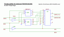
Pedja Rogic's I2S splitter with HEF4517 and 74157 is too slow for 24/192. This circuit inverts data, and creates 2 separate I2S streams with re-arranged data: L+ / L- in I2S stream #1 and R+ / R- in I2S stream #2 instead of L / R (input stream).
The splitter delays I2S data (shift registers) and uses a multiplexer (electronic switch) to select correct delayed signal:
001100 (WS input)
L1R1L2 (no delay)
---L1R1 (32 bit delay)
------L1 (64 bit delay)
I2S stream #1 (L+ / L-)
110011 (WS output = inverted WS input)
---L1-- (mux selects 32 bit non-inverted delay output when input ws=1)
------L1 (mux selects 64 bit inverted delay output when input WS=0)
I2S stream #2 (R+ / R-)
110011 (WS output = inverted WS input)
---R1-- (mux selects non-inverted non-delay output when input WS=1)
------R1 (mux selects inverted 32 bit delay output when input WS=0)
You could re-design this circuit using faster logic, there would be plenty of interference to tackle though.
John, I'm looking to create a balanced I2S feed to each of 2 DACs & I'm wondering how suitable the differential line drivers/receivers DS8921/22 are fro the job?. Would these be fast enough, low jitter? I know you've used them in your I2S synchronous re-clocker but this was for 16/44 - I'm looking at 24/192 signals.
Others have recommended using LVDS transmitters/receivers for low jitter & higher speed but can I use the differential output from a LVDS transmitter directly into the I2S input of a DAC?
What do you think is the best approach?
Pedja Rogic has published the I2S splitter shown which significantly differs from just inverting the data - is this a better way of doing the splitting?
DS8921/22 are a bit slow (specified @ 10Mbit / second) as 192 * 64 = 12.288 Mbit / second is required.
Faster LVDS logic is not free of jitter (I looked up some LVD transmitter / receiver chips and peak to peak jitter varied between 400 and 1500ps. It's up to you if you want to put these in the I2S signal path to improve performance.
I think the best approach is shortest possible I2S / clock interlink between source and DAC and no buffers or (differential) drivers in between, only a suitable synchronous reclocker if required. I would use a single (selected) DAC chip to achieve maximum transparency, detail and refinement.
Pedja Rogic's I2S splitter with HEF4517 and 74157 is too slow for 24/192. This circuit inverts data, and creates 2 separate I2S streams with re-arranged data: L+ / L- in I2S stream #1 and R+ / R- in I2S stream #2 instead of L / R (input stream).
The splitter delays I2S data (shift registers) and uses a multiplexer (electronic switch) to select correct delayed signal:
001100 (WS input)
L1R1L2 (no delay)
---L1R1 (32 bit delay)
------L1 (64 bit delay)
I2S stream #1 (L+ / L-)
110011 (WS output = inverted WS input)
---L1-- (mux selects 32 bit non-inverted delay output when input ws=1)
------L1 (mux selects 64 bit inverted delay output when input WS=0)
I2S stream #2 (R+ / R-)
110011 (WS output = inverted WS input)
---R1-- (mux selects non-inverted non-delay output when input WS=1)
------R1 (mux selects inverted 32 bit delay output when input WS=0)
You could re-design this circuit using faster logic, there would be plenty of interference to tackle though.
God loves a trier but you ain't God, obviously 🙂You never give up, don't you? How many threads do you have running around the www about your infinite number of problems and your infinite number of projects? Last hope seems to be John now. Good luck. 😉
Hi jkeny,
DS8921/22 are a bit slow (specified @ 10Mbit / second) as 192 * 64 = 12.288 Mbit / second is required.
Faster LVDS logic is not free of jitter (I looked up some LVD transmitter / receiver chips and peak to peak jitter varied between 400 and 1500ps. It's up to you if you want to put these in the I2S signal path to improve performance.
I think the best approach is shortest possible I2S / clock interlink between source and DAC and no buffers or (differential) drivers in between, only a suitable synchronous reclocker if required. I would use a single (selected) DAC chip to achieve maximum transparency, detail and refinement.
Pedja Rogic's I2S splitter with HEF4517 and 74157 is too slow for 24/192. This circuit inverts data, and creates 2 separate I2S streams with re-arranged data: L+ / L- in I2S stream #1 and R+ / R- in I2S stream #2 instead of L / R (input stream).
The splitter delays I2S data (shift registers) and uses a multiplexer (electronic switch) to select correct delayed signal:
001100 (WS input)
L1R1L2 (no delay)
---L1R1 (32 bit delay)
------L1 (64 bit delay)
I2S stream #1 (L+ / L-)
110011 (WS output = inverted WS input)
---L1-- (mux selects 32 bit non-inverted delay output when input ws=1)
------L1 (mux selects 64 bit inverted delay output when input WS=0)
I2S stream #2 (R+ / R-)
110011 (WS output = inverted WS input)
---R1-- (mux selects non-inverted non-delay output when input WS=1)
------R1 (mux selects inverted 32 bit delay output when input WS=0)
You could re-design this circuit using faster logic, there would be plenty of interference to tackle though.
Thanks John,
I wondered if there is any advantage to this form of i2S split streams (pic attached) rather than to just inverting the I2S stream & sending it to an identical DAC for the R-/L- analogue side ?
BTW, this I2S splitting was done for a TDA1541 DAC
Attachments

Jitter performance of LVDS parts
Which vendors have you looked at? I've been studying National and Fairchild and so far haven't noticed any specs in their datasheets specifically pertaining to jitter performance, so I'd appreciate a heads-up here.
Faster LVDS logic is not free of jitter (I looked up some LVD transmitter / receiver chips and peak to peak jitter varied between 400 and 1500ps. It's up to you if you want to put these in the I2S signal path to improve performance.
Which vendors have you looked at? I've been studying National and Fairchild and so far haven't noticed any specs in their datasheets specifically pertaining to jitter performance, so I'd appreciate a heads-up here.
Faster LVDS logic is not free of jitter (I looked up some LVD transmitter / receiver chips and peak to peak jitter varied between 400 and 1500ps.
On the devices I have looked up the worst case timing was 0.5ns = 500ps.
Hi Raymond,
I don't want to pull this thread OT - I really only posted here because I knew John had an I2S splitter in the past & wondered what his current experience was of how to do this.
500ps is a hefty enough extra jitter payload to add to the jitter already on the I2S clock, no?
Ray, what are you using to achieve your ES9022 balanced operation?
Others have recommended using LVDS transmitters/receivers for low jitter & higher speed but can I use the differential output from a LVDS transmitter directly into the I2S input of a DAC?
As the "Other" I wonder - do you go public with all your private conversations?
As to your question - no - as the signal are differential at +-0.3 volt and must be terminated with a resistor, and the +- 0.3 volt signal are not referenced to ground...
As the "Other" I wonder - do you go public with all your private conversations?
As to your question - no - as the signal are differential at +-0.3 volt and must be terminated with a resistor, and the +- 0.3 volt signal are not referenced to ground...
Ray, you aren't the "Other" - I was referring to another thread http://www.diyaudio.com/forums/digi...-issues-possible-resolutions.html#post2098114
I don't believe we ever talked about LVDS privately & I have never gone public with anything we have spoken of?
Edit: if you are referring to my statement about your balanced Es9022 use - it's in your sig 🙂
Last edited:
Hi Raymond,
Ray, what are you using to achieve your ES9022 balanced operation?
One inverter on the data stream to one of the DACs.
I may have mentioned that the MSB bit are the sign bit and the remaining 15 bits are the data.
By inverting the data stream you changes the polarity.
Funny that most people still believe that "16bit" are 16bit when it always have been 15bit value and 1 sign bit... Thus it can be 15bit positive and 15bit negative...
- Status
- Not open for further replies.
- Home
- Source & Line
- Digital Source
- Lossless SD-card player