Dear folks,
I work on my new split passive RIAA tube preamp and I found a "magic" issue.
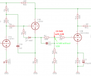
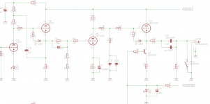
The input signal is amplified by a 5751 stage which has a boot straped cathode follower. After this CF a shelving filter for the 500Hz and 2122Hz frequency is attached. At 1kHz it create a -6.4dB loss. Using a simulation with LTSpice everything works fine so far. If I insert only the first stage tube (5751 ) I measure the correct loss of -6.4dB after the shelving filter.
But if I attach the next DC coupled simple amplifier stage using an ECC83 I measure a loss of -10.9dB after the shelving filter. So I loss 4.5dB somewhere🙁
What happens here? The input impedance of the dc coupled ECC83 should be several Meg ohms and not 30KOhm which create a drop of additional -4.5dB😡
Any idea what happens here ??
Thanks a lot for any hint.
Best Regards
Karsten
I work on my new split passive RIAA tube preamp and I found a "magic" issue.
The input signal is amplified by a 5751 stage which has a boot straped cathode follower. After this CF a shelving filter for the 500Hz and 2122Hz frequency is attached. At 1kHz it create a -6.4dB loss. Using a simulation with LTSpice everything works fine so far. If I insert only the first stage tube (5751 ) I measure the correct loss of -6.4dB after the shelving filter.
But if I attach the next DC coupled simple amplifier stage using an ECC83 I measure a loss of -10.9dB after the shelving filter. So I loss 4.5dB somewhere🙁
What happens here? The input impedance of the dc coupled ECC83 should be several Meg ohms and not 30KOhm which create a drop of additional -4.5dB😡
Any idea what happens here ??
Thanks a lot for any hint.
Best Regards
Karsten
Attachments
Is V2B drawing grid current? The bias window for an ECC83 is quite narrow. If the anode-cathode voltage is too low then the grid-cathode voltage will be small as in that circuit the valve is forced to carry some current so it will adjust its bias to achieve this.
Dear DF96
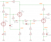
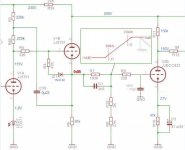
I mesured the DC voltages and put them into the part of the schematic. I do not see that the V2B will drawing some grid current.
I will try to measure this, but I think a normal multimeter is not sufficient enought to measure such a small current.
In fact: I do not fully understand in which circumstance a grid current will be drawn. The aim of DC coupling is to reduce possible distortion and phase shifting by the coupling capacitor. But if this is a wrong desig: i will change it. I think i makes sense to understand the issue befor simply change smaething.. 🙂
Thanks a lot for your help!!!
best Regards
Karsten
Attachments
you could probably make R9 (grid stopper) somewhat larger to detect any current drawn by the ECC832. Even simple DVMs are quite good in measuring mV at DC.
Hello Erik,
Nice idea! So I use a 4.7K grid stopper and measure 2mV. Take the 27.7V at R9/R7/C1/R25 to ground in account the DC resistance of V2B grid is:
Ig = UR9/R9 -> Ig = 42,5µA.
Rg = Ug/Ig -> Rg = 27.7V/42.5µA -> 651.7 KOhm
To get the measured loss of -4.5dB the shelving filter must be loaded with ~30K.
I´m confused now....😕
Best Regards
Karsten
May be the effect of miller capacity of the ecc83?
Well A is ~ 56 which means
Cmiller = Cgk + Cga(1+56)
Cmiller = 1.6p + 1.7p(1+56)
Cmiller = 98.5pF
Simulating the shelving filter with a capacitive load of 100pF will drop the output at 1Khz by 0.04dB only.
But thanks a lot! I forget to the Cmiller at the simulation. 🙂
Regards
Karsten
I'm on a plane so cannot get very detailed, but second stage operating point is really messed up. There should be no current through your riaa network. Note that cathode of the voltage amplifier stage should be roughly 101V - use 200k cathode resistor. This will give you 0.5mA plate current and roughly 190V on plate to start.
You use wrong part of ECC832 (half is ECC83, another half is ECC82).
1,2,3 pin is ECC83
6,7,8 pin is ECC82
BTW this schematic (as phono) is not optimal.
The second (half) 5751 anode current is too high (about 2mA, due to current of R7-R8).
Total gain is too low (36dB at 750Hz), gain error is about 0.5dB (10Hz..20kHz), with "large" hump at 750Hz.
1,2,3 pin is ECC83
6,7,8 pin is ECC82
BTW this schematic (as phono) is not optimal.
The second (half) 5751 anode current is too high (about 2mA, due to current of R7-R8).
Total gain is too low (36dB at 750Hz), gain error is about 0.5dB (10Hz..20kHz), with "large" hump at 750Hz.
Attachments
Last edited:
You use wrong part of ECC832 (half is ECC83, another half is ECC82).
1,2,3 pin is ECC83
6,7,8 pin is ECC82
Ohh, I did the same wrong pinning. The JJ ECC832 is System1 = ECC83= 6,7,8 and System 2 is ECC82 = 1,2,3.
So the pinning is correct.
BTW this schematic (as phono) is not optimal.
The second (half) 5751 anode current is too high (about 2mA, due to current of R7-R8).
Total gain is too low (36dB at 750Hz), gain error is about 0.5dB (10Hz..20kHz), with "large" hump at 750Hz.
Humm, Yess: 2mA. I will go back to load line of second half of 5751 but 2mA seemed not to hight for this type I think.
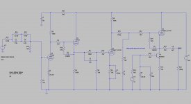
The RIAA is splitted in two parts and I show now only the first one ( 500Hz and 2122Hz ). The second 50Hz is "behind" V2B.
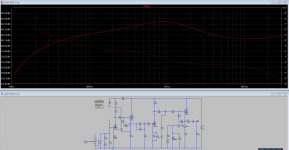
Using LTSpice and the whole schematic the gain error of RIAA is only 0.4dB max which is quite nice for me..
The original design is from tubecad.com 2007 ( http://www.tubecad.com/2007/09/blog0118.htm ) which I thought it is a very good base to start a split RIAA phono preamp.
Regards
Karsten
Last edited:
-0.6V from grid to cathode is small enough that grid current can flow.
That is a DC calculation. You need an AC (slope) calculation. For a wild estimate, assume that your measured 42.5uA arises from a 0.5V change. Then you get about 12k. I think that confirms that grid current is the cause.karsten21 said:Rg = Ug/Ig -> Rg = 27.7V/42.5µA -> 651.7 KOhm
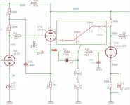
What are you trying to do 😕 Half of an inverted RIAA followed by a completely saturated triode 😱
Modified so it could function but don't ask me for what 😀
Mona
Hello Mona,
In general the RIAA should work. The simulation using LTSpice show a good result, not perfect but good enought for me.
And yes, there seemed to be a problem with the V2B triode. With help of DF96 we see, that there is some grid current. So I have to find out why. If you have an idea, please let me know.
I think this desig should work in general otherwise it would not printed at the tubecad.com blog.
Regards
Karsten
Hi Ketje,
Please see the simulated RIAA divergation.
But the reality is an other part 😡.
I have to investigate the V2B stage what happens here in the reality...
Regards Karsten
P.S. my git repository has just merged the LTSpice file... here is the correct one.
Please see the simulated RIAA divergation.
But the reality is an other part 😡.
I have to investigate the V2B stage what happens here in the reality...
Regards Karsten
P.S. my git repository has just merged the LTSpice file... here is the correct one.
Attachments
I already told you why, but I will spell it out in more detail. You have set the cathode current by requiring that the cathode sits around a particular voltage, with a particular cathode resistor value. You have set the anode voltage by fixing the anode resistor so it drops a particular voltage at that current. The valve thus has fixed cathode-anode voltage and fixed current. The only thing it can vary is the grid bias. So it chooses the grid bias which gives that anode current at that anode voltage. If this bias is not sufficiently negative (typically, at least -1V but could be up to -1.5V) then grid current will flow.karsten21 said:With help of DF96 we see, that there is some grid current. So I have to find out why. If you have an idea, please let me know.
Try reducing the anode resistor. This will raise the anode voltage and so allow more negative grid bias.
- Status
- Not open for further replies.
- Home
- Amplifiers
- Tubes / Valves
- Loss 4.5dB at DC coupling RIAA filter