Hi David,
I would choose to design the amp with the Full power Bandwidth upto 100KHZ ...and would implement Second order Low pass filter F=30KHZ @-3dB at the input to eliminate any HF interference....and would use only single compensation at VAS with 33pF 1000V ...for less sonic degradation..
regards,
K a n w a r
Hi, AndrewT,
What is a Thiel? Do you have a drawing of it?
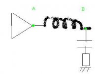
In many designs, the output has output inductor. What is the main purpose of this inductor (small value, uH, //with R before speaker)?
What is a Thiel? Do you have a drawing of it?
In many designs, the output has output inductor. What is the main purpose of this inductor (small value, uH, //with R before speaker)?
Hi, Kanwar,
Very nice 😀. The OL response is flat up to 100khz? You use folded cascode? Or do you use ordinary 3 stages topology?
One design that I see can have quite large OL bandwith while have quite some OL gain is Electrocompaniet/Otala amp. But they didn't use ordinary 3 stages topology to achieve that. Quite sophisticated approach there.
Do you use feedforward cap? (pF cap from VAS to inverting input)
I would choose to design the amp with the Full power Bandwidth upto 100KHZ ...and would implement Second order Low pass filter F=30KHZ @-3dB at the input to eliminate any HF interference....and would use only single compensation at VAS with 33pF 1000V ...for less sonic degradation..
Very nice 😀. The OL response is flat up to 100khz? You use folded cascode? Or do you use ordinary 3 stages topology?
One design that I see can have quite large OL bandwith while have quite some OL gain is Electrocompaniet/Otala amp. But they didn't use ordinary 3 stages topology to achieve that. Quite sophisticated approach there.
Do you use feedforward cap? (pF cap from VAS to inverting input)
Hi CBS240
Your circuit differs from conventionnality in its output stage, in some resistors of doubtul necessity around the current mirror and the Vas base, and in its regulated power supply for low power stage. See Doug Self's site for a better output scheme using emitter followers. The two first features probably explain why the Miller compensation makes your amp unstable.
~~~~~ Forr
§§§
ANDREW-T / LUMANAUW
My own explantion for the use of Zobel networks :
emitter followers (and coumpound pairs) are 100% feedback circuits.
An emitter follower can be considered as an amplifying circuit where the output and the feedback nodes are the same. If, for any reason, the gain at the output becomes higher than 1 or the current/voltage phase reaches 90° which combines with a phase lag near 90° in the device, it will oscillate. A Zobel network acts a compensation network, its aim is to ensure the gain is always less than 1 at high frequencies.
Modelling seems not to be so easy and in fact the adequate values are found experimentally. 100 nF + 4.7-10 Ohm usually do the trick. A very useful feature of this circuit is that it monitors very high frequency oscillations (some may not be visible on scopes) which heat the resistor : just touch it with your finger.
~~~~~~~~ Forr
§§§
Yes, I could probably replace the 2 diodes with a resistor in output stage, and scrap the base resistor on VAS. I suppose the 280 & 100 Ohm resistors in the mirror could go as well? The 28 Ohms in the mirror is for degeneration, but could probably be like 10 Ohms. 28 Ohm is the smallest SMD resistors I had.🙄 Most of this circuit is made with SMD's
AndrewT said:Hi Cbs,
neat trick using the voltage doubler before the regs.
Could the regs and/or the low rail caps be in part causing the odd stability behaviour?
Hi Andrew T,
The idea behind the voltage doubler and regs is so the VAS doesn't have to drive to the rail so as to keep more Vce on it and I can use larger emitter resistors for more linearity, yet still get rail to rail operation of the output stage. D4*H11 are only TO-220 devices. 30W is asking a lot from these. BTW, I was able to drive 2 Ohms...but the power rails sag to around 12V!. This is probably a good thing because the SOA of the outputs isn't quite as high as MJ21195.😀
CBS
Self uses an input stage with 2 * 3 mA, 2 * 100 Ohm as Re, and 2 * 68 Ohm in the current mirror. With matched transistors for the mirror, you can go lower, no need to change your 28 Ohm. I dislike the idea of a trim pot as Re in the diff pair : currents and gm in the diff pair should be very similar. Offsets are usually sufficiently low without it.
~~~~~~~~ Forr
§§§
lumanauw said:Hi, Kanwar,
Very nice 😀. The OL response is flat up to 100khz? You use folded cascode? Or do you use ordinary 3 stages topology?
One design that I see can have quite large OL bandwith while have quite some OL gain is Electrocompaniet/Otala amp. But they didn't use ordinary 3 stages topology to achieve that. Quite sophisticated approach there.
Do you use feedforward cap? (pF cap from VAS to inverting input)
What I use is as follows...
Input NPN Cascode loaded Differential (Error amp + VAS)-> NPN Emitter Follower(Bootstrapped Buffer) -> [Unity gain Level Translator]PNP Cascoded Driver -> NVMOS output...= Wide Bandwidth..achieveability...
I donot implement feedforward cap...instead a RC compensation at differential collectors plays the trick....
regards,
K a n w a r
Hi Forr,
I am surprised that you say a follower (CFP & EF) can have gain over 1.
If the phase of the load were 60degrees and the circuit shift was 90degrees leaving a phase margin of 30degrees (180-90-60=30). This is less than opamps aim for (>40degrees). Are you saying that if the margin gets too low the amp oscillates or if the gain is over 1 the amp oscillates? Which?
Help.
I am surprised that you say a follower (CFP & EF) can have gain over 1.
Can you explain this, a bit more detailed so that I can get it into my peanut of a brain.gain at the output becomes higher than 1 or the current/voltage phase reaches 90° which combines with a phase lag near 90° in the device,
If the phase of the load were 60degrees and the circuit shift was 90degrees leaving a phase margin of 30degrees (180-90-60=30). This is less than opamps aim for (>40degrees). Are you saying that if the margin gets too low the amp oscillates or if the gain is over 1 the amp oscillates? Which?
Help.
Hi ANDREW-T,
This reminds me of one of electronicians Murphy's laws :
an amp always oscillates, an oscillator never wants to start to oscillate.
Am I wrong ? My thought is that, if an emitter follower oscillates because of its load, it is due to the fact that its emitter receives a signal which, due to some phase lag, becomes positive feedback. Combined with the input, the oscillation is maintained because the gain is then higher than 1.
~~~~~~~ Forr
§§§
A few very general remarks from my experience:
The Zobel does not work with all designs. The purpose is laudible enough, but folks sometimes overlook that during the "cut-in" phase there is phase shift that the amp might not like at that frequency. I have used designs that were stable from load to open circuit, that became unstable with the use of a Zobel. In other cases it was advantageous. A Spice analysis usually points this out.
The use of Cdom can raise problems in some topologies. It is OK to design nicely satisfying Nyquist/Bode requirements, but with what sort of open-loop bandwidth? As soon as this cuts into the audio band there is possibility of transient oscillation manifesting as listener fatigue, even though this might not be evident during steady-state tests. (The feedback "arrives late".) There was an informative article in Electronis World some time ago (unfortunately I cannot recall the date) by Dr John Ellis on the alternative of input-lag-output-lead (ILPL) feedback, making quite a strong case for avoiding phase-lag compensation inside the feedback loop. I personally always tried to achieve a loop bandwidth of 20KHz before needing phase corrective measures (as one will have to in the end), leaving 0 phase-shift within the audio band - a safe policy and one that can be reached.
Without being specific (and thus not contributing usefully!) the final yardstick IMO is an acceptable spectrum analysis. Designing high-gain circuits and then managing to achieve stability with 50+ dB of NFB may be an admirable academic achievement, but such designs often leave something to be desired in avoiding high order harmonic distortion. (Most members will know that THD has become a meaningless parameter precisely because of this.) I try to stay below 30 dB of NFB for high quality "transparent" quality.
Finally there is the point first raised by Amplifierguru many years ago of the impedance of the power supply OVER THE WHOLE AUDIO SPECTRUM. Spurious contribution to unacceptable reproduction may result where this is wanting.
The use of a small inductance (I cannot recall whether this was answered) in serie with the load is to off-set cable capacity in circuits that are sensitive to this and usually comes into play at above 50 KHz. It should have no effect in the audio band.
Regards all.
Hi, Johan,
Thanks for the explenation. 😀
In post #19, AndrewT mentioned 1 important function of this Zobel.
This makes me wonders more :
Why don't we just make a design that has low OL gain? Something like 30-40dB OL gain, with 20dB FB/20dB CL gain?
With this, we can eliminate using miller dominant pole and zobel network without any danger?
Or in such small gain design, miller and zobel should also be there?
Thanks for the explenation. 😀
In post #19, AndrewT mentioned 1 important function of this Zobel.
If one of Zobel's function is like this, I think like it or not we should always use Zobel (100nF+10R), and then try to overshoot the oscilation elsewhere (if the design just oscilates with zobel attached instead)2. the network attenuates interference picked up by the speaker/cable before you inject this interference through the feedback loop into the inverting input. The Thiel is more effective at this.
This makes me wonders more :
Why don't we just make a design that has low OL gain? Something like 30-40dB OL gain, with 20dB FB/20dB CL gain?
With this, we can eliminate using miller dominant pole and zobel network without any danger?
Or in such small gain design, miller and zobel should also be there?
Lumanauw,
Just before going to bed (as I should have done a long time ago);
Andrew T is quite correct but that is a secondary advantage of the Zobel network, also mercifully one is usually in an environment where pick-up of rubbish through speaker cable is not a great danger (although it should never be overlooked, and some circuits are particularly prone to this. But that is another subject).
I am afraid that in most decent designs one will never entirely avoid the requirement of having to do some sort of phase compensation for optimum stability, although this is certainly eased by careful design before feedback. (Always the old principle: Make the best design you can, and then use NFB to improve it; never use NFB to try to correct an inferior design.) Basic requirements will always be for some sort of dominant pole correction; point is that the Miller C is not the only way. I may have been vague in that respect. Not to repeat, but I always try to keep high frequency (and low!) compensation outside the audio band - and then filter any input outside these limits to get rid of signals there that could just cause problems in the reactive parts of the total band without contributing to what is wanted.
Johan makes the very best of points...
Make your system as linear as possible before the addition of feedback. This cannot be emphasized enough... it is the essential key. Feedback brings its own set of problems... the more feedback... the more problems... in a general way.
The better your open loop system is; the less feedback you need to correct it.
Hi David,
Low Open Loop Gain/Low Feedback Factor would also decrease the Damping factor at the output node....
K a n w a r
Low Open Loop Gain/Low Feedback Factor would also decrease the Damping factor at the output node....
K a n w a r
An excellent book which used to be a bible to me was Tobey,Graeme,Hueslman "Operational Amplifiers: Design, and Applications" McGraw Hill 1971. Unfortunately it walked.
Anything by Jerald Graeme (mgr IC devel group at Burr Brown) like "phase Compensation Perks up Composite Amplifiers" published ED Aug 19 1993 should help. The composite stages needn't be op-amps just single pole stages. Lots of Nyquist stuff there. Two poles great.
Great bedtime reading.
Cheers,
Greg
Further to my post #32, I saw that I got it slightly wrong: The procedure advocated by John Ellis is the phase lead input lag (PLIL) configuration. The article is "Audio Power Amplifier Frequency Compensation" and appeared in Electronics World, March 2003.
John makes a strong case supported by phase plots and oscillographs of the improved results. It is very worthwhile reading.
John makes a strong case supported by phase plots and oscillographs of the improved results. It is very worthwhile reading.
- Status
- Not open for further replies.
- Home
- Amplifiers
- Solid State
- Loop gain question