felixx said:ricobasso
I tryed to ask you some things but I can't contact you.
I have now enabled private messaging. I guess this was why you could not contact me.
I agree there will be a loop when you only have one transformer but the loop area can be reduced by changes to the routing of the wires and twisting wherever possible. If the loop area=0 there will be zero hum pickup.
I have been told that toroid transformers can produce very directional "spears" of magnetic leakage. You could use a search coil connected to an amplifier to map these out in 3-D. Then turn the transformer to minimise the field in the direction at right angles to the loop.
Two transformers seems fanatical to me. Don't forget that even with two transformers there will still be a high impedance loop via the interwinding capacitance! I don't have a feel for how low you want the hum to be, but you have to stop somewhere.
I have now enabled private messaging. I guess this was why you could not contact me.
Yes.That is the reason can't contact you.Still is that....
I agree there will be a loop when you only have one transformer but the loop area can be reduced by changes to the routing of the wires and twisting wherever possible.
I agree with you.
If the loop area=0 there will be zero hum pickup.
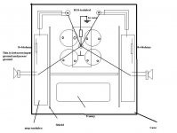
I think that is impossible or I can't understand exactly.Check the pic.
I have been told that toroid transformers can produce very directional "spears" of magnetic leakage. You could use a search coil connected to an amplifier to map these out in 3-D. Then turn the transformer to minimise the field in the direction at right angles to the loop.
I tryed to move the tranny in all positions and angles and yes-the stray effect is different.I choose the silent mode.
Attachments
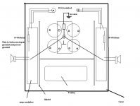

In that pic. is how I intend to do but this is possible only with two power supply's.
What do you think?
Zero loop,zero humm,zero noise.
Maybe this is impossible.
What do you think?
I don't have a feel for how low you want the hum to be, but you have to stop somewhere.
Zero loop,zero humm,zero noise.
Maybe this is impossible.
Attachments
Hi Felixx,
your power amp audio ground is in the wrong place.
You have attached it to the zero volts common plate between the PSU smoothing caps.
Look at the short link running up from the zero volts connection to the resistor/disconnecting network to the chassis.
Move the two speaker return wires half way up that link.
Move the signal grounds and the PCB power grounds to this same star ground.
This new arrangement isolates the charging pulses in the rectifier/smoothing caps routes from the audio ground.
Now try an experiment.
Disconnect the signal ground between PCB and the input cable screen. Connect a link from the input RCA barrel to that new audio star ground.
Does it help reduce the hum/buzz on any of the offending sources?
An alternative is to disconnect the signal ground on the PCB from the audio ground and pass the PCB signal ground out through the input cable screen to the RCA barrels then back the the audio ground with that new link you added in the last paragraph.
Hi Andrew!
I tryed that but the noise is more obvious.
More noise with that mod.
The noise apear only when I have both left to right connections.Loop.
Off course,the stray field "attached" is something else.
Disconnect the signal ground between PCB and the input cable screen. Connect a link from the input RCA barrel to that new audio star ground.
I tryed that but the noise is more obvious.
your power amp audio ground is in the wrong place.
You have attached it to the zero volts common plate between the PSU smoothing caps.
More noise with that mod.
The noise apear only when I have both left to right connections.Loop.
Off course,the stray field "attached" is something else.
Attachments
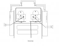
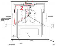
Felix as far as I can see you still have a huge loop area (shown in red in my attachment) in your last picture (case 3). You need to take the left input cable over to the right as I described in an earlier post. I will try to draw a picture if I get some time.
Attachments
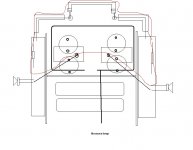
This is what I meant. The right input shielded cable should follow the thick red line I have drawn in order to reduce the loop area. You should tie or twist the left, right and ground cables to keep them together.
I apologise if it offends your sense of symmetry. I'm sure you could devise a better way that still keeps the area small.
I apologise if it offends your sense of symmetry. I'm sure you could devise a better way that still keeps the area small.
Attachments

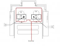
Connect the input RCA grounds to each other at the connectors and then connect with ONE wire to power supply common, not two like in your last picture. Also make sure you remove the wires from power supply common to input ground if you haven't done that already. Input ground from each board should go through the shields and meet at the inputs. The 10 ohm resistors make sure there is no loop around the amplifier. Connecting only one wire from power supply to the inputs makes sure the loop that is still left has a very small area.
This makes loop 1 as small as possible which is what matters. Loop 2 does not matter as no significant current can flow through it due to the separating resistor. The voltage that falls over the separating resistor is only amplified one time instead of by the gain of the amplifier so the hum should be inaudible.
Observe that the shield is now connected at both ends! This is VERY important.
Optimally, the star ground should be moved off the plate as Andrew says too but it may not be needed. Current between capacitors and transformer must not be allowed to flow through the star ground point.
Observe that the shield is now connected at both ends! This is VERY important.
Optimally, the star ground should be moved off the plate as Andrew says too but it may not be needed. Current between capacitors and transformer must not be allowed to flow through the star ground point.
Attachments
I suggested the same but he said.megajocke said:Connect the input RCA grounds to each other at the connectors and then connect with ONE wire to power supply common, not two like in your last picture. Also make sure you remove the wires from power supply common to input ground if you haven't done that already. Input ground from each board should go through the shields and meet at the inputs. The 10 ohm resistors make sure there is no loop around the amplifier. Connecting only one wire from power supply to the inputs makes sure the loop that is still left has a very small area.
I tryed that but the noise is more obvious.
Wasn't that with the input ground disconnected from the screen? The loop breaking resistors won't do any good in that case. The screen is used to sense the ground potential at the input terminals, the amplifier only amplifies the difference by its gain. The voltage on the screen relative to amplifier power ground is only amplified one time.
Without the screen connected at both ends the loop voltage will fall between the RCAs' shells and the input ground. This voltage will be amplified by the gain of the amplifier when another unit is connected.
Without the screen connected at both ends the loop voltage will fall between the RCAs' shells and the input ground. This voltage will be amplified by the gain of the amplifier when another unit is connected.
megajocke said:Loop 2 does not matter as no significant current can flow through it due to the separating resistor.
Are you sure about this? If we assume that without the 10 Ohm resistor the loop resistance would be around 0.1 Ohm then the resistor will reduce the loop current by 40dB. Maybe this is not enough? Difficult to tell without being there and listening.
You might have a point, but the 10 ohm resistor seems to usually be enough. What matters is the voltage drop over the shield of the input cable, because that will be amplified. It should be possible to get this resistance pretty low.
Splitting the PSU's should be fine! 🙂 But isn't that cheating? 😉
Is your "Case 5" still silent when connecting other equipment? It should be possible for it to work.
I'm surprised though it started humming when connecting the RCAs to the PS with a single wire. What stuff is connected to the input ground on the amplifier boards? Is the ground of the feedback network connected there? It would be interesting to see a schematic of your amp. 🙂
I'm surprised though it started humming when connecting the RCAs to the PS with a single wire. What stuff is connected to the input ground on the amplifier boards? Is the ground of the feedback network connected there?
On all experiments I use a single (mono) interconnect cable to bring the RCA's in parallel.
I have an active cross. for this amp connected on inputs.On the output of the cross is a double log. potentiometer for level.This is why I choose to experiment only with the interconnect because is the same thing.
The schematic is simple as possible.
Attachments

Vali,
Cut the 100nF capacitor in parallel with 10ohm on input ground.
Add a follower between VAS and output stage. The output capacitance seen by the VAS is huge at HF without drivers (you have multiple parallel FETs in output stage). An amp without drivers is suitable only for subwoofer.
The 2 diodes CCS has a poor PSSR. There is a regulated power supply for the LTP and VAS?
Mihai
That looks nice, the cap between VAS bases might cause som strange effects depending on the power supply, but it probably has nothing to do with the hum. 🙂
I didn't really get if you are still having problems with it, you said it was silent in "Case 5" when you didn't connect them together. But case 5 doesn't show any connection to other equipment, and an amplifier that you can't connect a signal to isn't too useful maybe? 😀
Did it start humming when connecting together the grounds at the RCAs or was it when connecting to the power supply? Did it do this with open inputs, shorted inputs, inputs connected to each other with the mono cable or was it connected to the crossover? Was it in more than one of these situations?
Maybe the 100n capacitor is a problem, it is usually not used in the amplifier. Usually one is used in the isolation circuit between chassis and amplifier ground though.
The mono RCA cable won't be the same thing as the real thing, in the real thing the inputs are connected to ground, not each other. The mono rca won't show you when you have a contaminated ground at the RCAs for example. Closer to the real thing would be to take RCAs in stereo and short together all four conductors at the other end.
- Status
- Not open for further replies.
- Home
- Amplifiers
- Solid State
- Loop breakers