Does anybody remember that Williamson amplifier from the 60's that used direct coupling from the phase inverter section into the control grid of the push-pull, using an ultralinear output transformer?
I put together one, based on squematics that used 12AX7's and EL84. That was when I was young, about 30 years ago. I've been looking for those plans but I think I lost them.
Thanks,
Burt.
I put together one, based on squematics that used 12AX7's and EL84. That was when I was young, about 30 years ago. I've been looking for those plans but I think I lost them.
Thanks,
Burt.
Last edited by a moderator:
That was fast! That's exactly as I remember the last stages. Do you have the pre-amp also? I remember it used 12AX7,12AT7 and 12AU7. It had the tone control section between the last two tubes I think.
Thanks a lot!
Burt.
Thanks a lot!
Burt.
You are welcome! 🙂Thanks a lot!
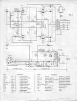
Please see original schematic:
The Williamson Amplifier (Articles reprinted from "Wireless Word")
And read the topic here, at forum:
http://www.diyaudio.com/forums/tube...nd-direct-couple-el84-amplifier-question.html
Kind Regards, Konstantin
The schematic levelfive posted is not Williamson. That circuit employs a paraphase splitter (has gain).
Williamson topology employs a triode voltage amplifier DC coupled to a "concertina" phase splitter. The splitter is cap. coupled to a differential amp that's cap coupled to the "finals". Williamson used 2X 6SN7s for the 4 small signal triodes. At least 1 implementation (by Heath) uses 2X 12AU7s.
Williamson topology employs a triode voltage amplifier DC coupled to a "concertina" phase splitter. The splitter is cap. coupled to a differential amp that's cap coupled to the "finals". Williamson used 2X 6SN7s for the 4 small signal triodes. At least 1 implementation (by Heath) uses 2X 12AU7s.
The schematic levelfive posted is not Williamson.
Hi, Eli
Mullard 5-10 and Dynaco ST-70 are also very similar to Williamson circuit design. Williamson design is the basic and each follower make their designs slightly different, with little improvement 😉
Williamson circuit topology means how the voltage amp, phase splitter and final stage tubes are connected at the block diagram level.
Prooflinks:
Williamson amplifier - Wikipedia, the free encyclopedia
Mullard 5-10 - Wikipedia, the free encyclopedia
Mullard 5-10 Ten Watt Amplifier
Last edited:
Mullard style topology, with voltage amplifier DC coupled to a differential splitter and on to the "finals" is quite different than Williamson style. Mullard style is not nearly as vulnerable to instablility as Williamson, which makes it (IMO) a better candidate for use with O/P "iron" that's not creme de la creme.
A voltage amplifier DC coupled to a "concertina" phase splitter and on to the "finals" was used by Fisher and Scott, as well as Dyna. Fisher avoided a pentode in the voltage gain position by sticking to "12" W. and 7591s as "finals". Dyna's ST35 uses 12DW7s in the small signal "holes".
A voltage amplifier DC coupled to a "concertina" phase splitter and on to the "finals" was used by Fisher and Scott, as well as Dyna. Fisher avoided a pentode in the voltage gain position by sticking to "12" W. and 7591s as "finals". Dyna's ST35 uses 12DW7s in the small signal "holes".
The squematics sent by levelfive are exactly what I had. I built it in the 70s, it sounded great for me at that time and I don't remember ever had any problems with inestability. If it's not pure Williamson design I don't know, I'm only a farmer with some time to spare in my shop when it's too hot outside to be working in the fields. I would like to find the squematics for the pre-amp I did for this amp. I'm thinking to put them together again and try them with my Hartsfields.
Thanks
Thanks
- Status
- Not open for further replies.
- Home
- Amplifiers
- Tubes / Valves
- Looking for Williamson schematic