Koinichiwa,
I am looking for someone with background in PAL (or similar programmable logic arrays) Programming & Design for co-operation on a DAC project of mine.
The key area of design where I lack skills and tools and have no interest in obtaining such (never mind time) is to do with a FIFO based Databuffer including a retiming via external variable clock (programmable dividers like AD or PLL's like BB) which is controlled to keep a broad sync with the input signal and thus follow it but at the with good short term stability for high jitter rejection.
I have a pretty good idea as to how this can be implemented but no interest to design the neccesary glue logic around CMOS Chips, so programmable logic is needed as glue between this whole shooting match and one would need to draw a PCB (which again I can do but lack the time).
Implementing this well should give a very low Jitter datastream to the actual DAC, regardless how crappy the transport is, while using a standard Cirrus Logic receiver, allowing now theoretically 192KHz/24 Bit operation. For my own use the DAC will be zero oversampling of course and use PCM1704 with some nice tricks.
What I would percieve as doable and possibly interresting for the DIY Audio community is to design the DIR Input and Memory Buffer section as module board, with a buffered clock output on SMA (also an I2S or similar suitable data feed) to feed a reclocker on a DAC Board build by whoever wishes to use the re-timing section.
It matters zip if you stick a Non Oversampling TDA1543 on the end or choose to implement one of the latest newfangled Bitstream/Multibit Hybrids that everyone seems to be so fond of, with gobs of Digital Filtering. Anyones call.
Such a unit may be offered commercially or PCB only by whoever co-operates in the project or be simply published in Audio Express or wherever. This thing may suit an EE Student with a conventional, well measuring DAC on the end as a good final year project as well.
Whoever has the time and interrest to work on this needs to figure out their own angle, as I can't afford to pay for the design effort involved. I would only like to be able to use the results for my own stuff.
I would ideally like someone in the south of England (or even London) so it is possible to meet up and hash out key points over a few pints.
Sayonara
First of all, good luck with this project.
Proper implementing PLD’s is not task you learn in a few months indeed.
Please come up with a good block-diagram. Curious about it.
I see no use for shift registers as an “elastic store”. Jitter never crosses the boundaries of the width of the data pulses coming out of a transport unless you have a very, very bad transport. So you are always being able to resample the data directly with an ultra-low-jitter-recovered clock, provided it is a synchronous clock.
Very good PLD design tools are free on the internet:
http://www.latticesemi.com/products/devtools/software/ispLEVER-starter/index.cfm
But be warned. PLD’s are very jittery devices regarding the very low levels of jitter needed for good digital audio.
🙂
Koinichiwa,
I have used their ancestors in the 1980's, so I supect I can wise up (and I can still program in Assembler), but I really lack the time.
Flow chart too for the process? No sweat.
[/B][/QUOTE]
I do.
Sure. What I am really aiming at is a system that does not rely on a "pulled" X-tal (VCXO) for this clock, but uses a mechanism that can be "pulled" from 32KHz to 192KHz AT LEAST.
Using a decent high frequency X-Tal with a suitable programmable and variable downshift will give a low jitter widely pullable clock at very low cost.
Using a long FIFO will allow a very low rate of change in this clock, so it tracks only the AVERAGE frequency of the source, not the actual, eliminating jitter above the cycle of the lowest increment in time of changing the clock.
The clock needs to change only with buffer over- or under-run, using the right combo of buffer and logic gives "varispeed" ability where the larger the rise (or fall) in buffer length the faster the new clock is changed.
And the slower the rate of change in the source clock (usually constant) the lower the rate of change with the new master clock, putting in truely "locked" condition jitter rejection well below the 1Hz mark. Theoretically at least, anyway.
Yes, so is Linux. I still pay Bill "W" Gates for his WXP Sotware nevertheless, because I don't have time enough to learn Linux well enough. Yet at work a few minor Servers run Linux and where set up by Students on work experience.
I'm looking for the here. It's not that I cannot, but the poblem to me is ultimatley sufficient peripheral that I cannot be bothered. My current DAC has a dual PLL and is fairly low on jitter, but it is 16/44.1 only.
Which is why want them only for the control functionality to work out if the buffer grows or shrinks (and ideally how fast) and react to this by adjusting the programmed low jitter clock source apropriatley.
All the PAL stuff will be way out of the "signal" lineage and hopefully, once the "lock" has been obtained will be completely inactive at all...
Sayonara
Pjotr said:First of all, good luck with this project.
Proper implementing PLD’s is not task you learn in a few months indeed.
I have used their ancestors in the 1980's, so I supect I can wise up (and I can still program in Assembler), but I really lack the time.
Pjotr said:
Please come up with a good block-diagram. Curious about it.
Flow chart too for the process? No sweat.
[/B][/QUOTE]
Pjotr said:
I see no use for shift registers as an “elastic store”.
I do.
Pjotr said:
Jitter never crosses the boundaries of the width of the data pulses coming out of a transport unless you have a very, very bad transport. So you are always being able to resample the data directly with an ultra-low-jitter-recovered clock, provided it is a synchronous clock.
Sure. What I am really aiming at is a system that does not rely on a "pulled" X-tal (VCXO) for this clock, but uses a mechanism that can be "pulled" from 32KHz to 192KHz AT LEAST.
Using a decent high frequency X-Tal with a suitable programmable and variable downshift will give a low jitter widely pullable clock at very low cost.
Using a long FIFO will allow a very low rate of change in this clock, so it tracks only the AVERAGE frequency of the source, not the actual, eliminating jitter above the cycle of the lowest increment in time of changing the clock.
The clock needs to change only with buffer over- or under-run, using the right combo of buffer and logic gives "varispeed" ability where the larger the rise (or fall) in buffer length the faster the new clock is changed.
And the slower the rate of change in the source clock (usually constant) the lower the rate of change with the new master clock, putting in truely "locked" condition jitter rejection well below the 1Hz mark. Theoretically at least, anyway.
Pjotr said:
Very good PLD design tools are free on the internet:
Yes, so is Linux. I still pay Bill "W" Gates for his WXP Sotware nevertheless, because I don't have time enough to learn Linux well enough. Yet at work a few minor Servers run Linux and where set up by Students on work experience.
I'm looking for the here. It's not that I cannot, but the poblem to me is ultimatley sufficient peripheral that I cannot be bothered. My current DAC has a dual PLL and is fairly low on jitter, but it is 16/44.1 only.
Pjotr said:
But be warned. PLD’s are very jittery devices regarding the very low levels of jitter needed for good digital audio.
Which is why want them only for the control functionality to work out if the buffer grows or shrinks (and ideally how fast) and react to this by adjusting the programmed low jitter clock source apropriatley.
All the PAL stuff will be way out of the "signal" lineage and hopefully, once the "lock" has been obtained will be completely inactive at all...
Sayonara
Hi,
Thanks for clarifying. If I understand it right you intend to build a digital implemented PLL.
A PLL is basically a narrow band-pass filter concerning side band noise. Whether it is implemented analog or digital, all the basic rules about loop stability, pull range, catch range and so on still remains valid. But what ever you do, you stay limited to the side band noise of the reference (master) oscillator.
The quality of the master oscillator is mainly dependent of de Q-factor of the used crystal, proved the other electronics is done properly.
By building a purely digital PLL, you can’t avoid “clock pulse jumps”, to name it and the associated meta-stability. I am afraid this will do no better than a good PLL with a pulled X-tal oscillator as Guido did.
But I see, you want to build a PLL that is universal for all sampling frequencies in use today. The Crystal receiver chips have flags for frequency detection. If you make use of them you can also use 2 pulled X-tal reference oscillators: One for multiples of 44.1 kHz and one for multiples of 48 kHz. Looks a lot simpler.
For me such a clock upgrade is actual because I want to upgrade the clock circuitry of my M-Audio Superdac.
Regards 🙂
Koinichiwa,
Possibly. I somehow think not. What I have in mind is system that I'm familiar with in process controll applications. Once the "lock" is achieved the system has no or absolutely minimal activity of control, this is certainly not really the case the with analog PLL's I worked with. So there are similarities, but I would contend that the intended principle is superior to an analogue PLL once "lock" has been achieved.
My idea is to have the change of clock "varispeed". If there is a fast buffer "overrun" or "underrun" occuring the clock spped is changed more rapidly, however if you have a very small clock difference you only need to change the clock once every few seconds or even minutes by the smallest step.
The smallest step of programmable clock divided by two determines the maximum deviation between the clocks once "lock" is achieved. The AD9850 has an output tuning resolution of 0.0291Hz.
If we take a CD "retime" master clock of 11.2896MHz and have a FIFO buffer set (wee need three to make that easy to work - thanX to the other Guido for that hint) of the shortest type (256bit each) and aim to allways keep the middle buffer changing between full and empty we should have no activity in the controller once locked for hours at a time.
Yes, such a system will be relatively slow to settle to a full lock, but if we have it on for a while it MUST tend to a minimum deviation. I suspect that simply pre-setting the clock from the input frequency information from the DIR Chip will be enough to keep the first clock change down to a few seconds away.
So an anlogy to the function of a PLL exists but due to the digital nature of the system it is possible to settle to an absolute steady state with no activity.
Sure. But our clock pulse jumps (theoretically) are at 0.0291Hz out of 11.2896 MHz or 0.0026 PPM.
As for Guido's pulled VCXO, to cover 44.1KHz, 48KHz, 88.1KHz, 96KHz, 176KHz and 192KHz sample rates you ned an awfull lot of circuitry.
And all these frequencies may be encountered at some time from the Digital out of a universal DVD Video/Audio Player, depending if you play a DVD Movie, a CD or an Audio DVD. Hance my thought that all these Frequencies must be transparently handeled. And this of course is also the need for the Memory buffer as the clock in these things is positively dibolical.
The downside of this implementation is that it is a little past "kitchen table" electronics, but implemented well and sold as assebled module I suspect you would pick up both OEM's to incorporate this in their gear and it would eb an easy upgrade. Done in SMD the whole board can be tiny.
Sayonara
Pjotr said:Hi,
Thanks for clarifying. If I understand it right you intend to build a digital implemented PLL.
Possibly. I somehow think not. What I have in mind is system that I'm familiar with in process controll applications. Once the "lock" is achieved the system has no or absolutely minimal activity of control, this is certainly not really the case the with analog PLL's I worked with. So there are similarities, but I would contend that the intended principle is superior to an analogue PLL once "lock" has been achieved.
My idea is to have the change of clock "varispeed". If there is a fast buffer "overrun" or "underrun" occuring the clock spped is changed more rapidly, however if you have a very small clock difference you only need to change the clock once every few seconds or even minutes by the smallest step.
The smallest step of programmable clock divided by two determines the maximum deviation between the clocks once "lock" is achieved. The AD9850 has an output tuning resolution of 0.0291Hz.
If we take a CD "retime" master clock of 11.2896MHz and have a FIFO buffer set (wee need three to make that easy to work - thanX to the other Guido for that hint) of the shortest type (256bit each) and aim to allways keep the middle buffer changing between full and empty we should have no activity in the controller once locked for hours at a time.
Yes, such a system will be relatively slow to settle to a full lock, but if we have it on for a while it MUST tend to a minimum deviation. I suspect that simply pre-setting the clock from the input frequency information from the DIR Chip will be enough to keep the first clock change down to a few seconds away.
So an anlogy to the function of a PLL exists but due to the digital nature of the system it is possible to settle to an absolute steady state with no activity.
Pjotr said:
By building a purely digital PLL, you can’t avoid “clock pulse jumps”, to name it and the associated meta-stability. I am afraid this will do no better than a good PLL with a pulled X-tal oscillator as Guido did.
Sure. But our clock pulse jumps (theoretically) are at 0.0291Hz out of 11.2896 MHz or 0.0026 PPM.
As for Guido's pulled VCXO, to cover 44.1KHz, 48KHz, 88.1KHz, 96KHz, 176KHz and 192KHz sample rates you ned an awfull lot of circuitry.
And all these frequencies may be encountered at some time from the Digital out of a universal DVD Video/Audio Player, depending if you play a DVD Movie, a CD or an Audio DVD. Hance my thought that all these Frequencies must be transparently handeled. And this of course is also the need for the Memory buffer as the clock in these things is positively dibolical.
The downside of this implementation is that it is a little past "kitchen table" electronics, but implemented well and sold as assebled module I suspect you would pick up both OEM's to incorporate this in their gear and it would eb an easy upgrade. Done in SMD the whole board can be tiny.
Sayonara
Hello,
I’d be interested to hear more about you project as I’ve recently been considering something similar myself, although implemented more in programmable logic.
I’ve recently started using the Lattice 5000MX series CPLD devices at work and the 512 macrocell parts that I use have up to 256 Kbits of memory that can be configured however you like. I’m thinking about implementing a buffer in dual port RAM so the transport clocks the data in and I use an VCXO (or OCXO) to clock it out. I believe this method is used by Chord Electronics in their DAC64 product:
http://195.40.133.90/website/products/dac64.htm
The Lattice devices also have two onboard PLLs with jitter spec’ed at something like 250ps max although they did measure more like 100ps in the lab (application is 20MHz in -> 66MHz out). Not too great really….
The only downside is that most CPLDs and FPGAs are only available in surface mount QFP and BGA packages which make them hard to mount onto a PCB. Hard, but not impossible…..
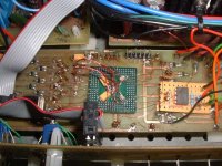
The pic (assuming it attaches - not shown in preview!) is a Xilinx CPLD which I use in my pre-amp for various duties but mainly for decoding the Sony SIRCS remote control protocol. I did this so that I could use an old Sony TV remote to control volume, source selection, on/off etc. It's a 272-pin BGA dead-beetled and wired to the main PCB. Clock is only 4MHz.
Anyway, I haven’t given my DAC project too much thought so I’m not sure how feasible it is. I’m kind of reluctant to commit to your project (due to a complete lack of time!) but let me know how much glue you need (and what PLD devices you’re considering) and I’ll try to help.
Nice one,
David.
I’d be interested to hear more about you project as I’ve recently been considering something similar myself, although implemented more in programmable logic.
I’ve recently started using the Lattice 5000MX series CPLD devices at work and the 512 macrocell parts that I use have up to 256 Kbits of memory that can be configured however you like. I’m thinking about implementing a buffer in dual port RAM so the transport clocks the data in and I use an VCXO (or OCXO) to clock it out. I believe this method is used by Chord Electronics in their DAC64 product:
http://195.40.133.90/website/products/dac64.htm
The Lattice devices also have two onboard PLLs with jitter spec’ed at something like 250ps max although they did measure more like 100ps in the lab (application is 20MHz in -> 66MHz out). Not too great really….
The only downside is that most CPLDs and FPGAs are only available in surface mount QFP and BGA packages which make them hard to mount onto a PCB. Hard, but not impossible…..
The pic (assuming it attaches - not shown in preview!) is a Xilinx CPLD which I use in my pre-amp for various duties but mainly for decoding the Sony SIRCS remote control protocol. I did this so that I could use an old Sony TV remote to control volume, source selection, on/off etc. It's a 272-pin BGA dead-beetled and wired to the main PCB. Clock is only 4MHz.
Anyway, I haven’t given my DAC project too much thought so I’m not sure how feasible it is. I’m kind of reluctant to commit to your project (due to a complete lack of time!) but let me know how much glue you need (and what PLD devices you’re considering) and I’ll try to help.
Nice one,
David.
Attachments
This is all very interesting.
An easy to implement soft buffer would be nice.
What I would like to see is say 64 pins or so feeding discrete current sources with some sort of randomization and at high frequency (sorry Thorsten!)
Or, provisions for feeding a number of parallel DAC chips staggered by a small number of (high frequency) clock cycles. 4-16 parallel staggered DAC chips seems just the ticket .... (they need to be current out for this to work).
And of course it would be nice to get digitally inverted signals to drive single ended DAC's "the other way" to create a balanced output signal.
Anybody else interested in either of these approaches?
Petter
Hi,
It looks this becomes a major project. I think it is worth to discuss it more extensively because it is an awful load of work. I think we should limit it to a “jiiter free” data steam/clock to the DAC chip.
Some remarks:
The mentioned AD9850 DDS chip is a nice signal generator. But I have my doubts. Such chips exhibit a large amount of phase noise, or more precisely “phase jumps”, if the ratio of clock frequency and output frequency is not very large. Also the jitter specs of the build-in comparator are not that good.
David, the mentioned PLD’s/CPLD’s are quite expensive for DIY
Regards
Pjotr,
You're right - I wouldn't recommend using a large CPLD in DIY design collaborations because they are quite expensive. The part I used for my remote control decoder is about $15, plus you need programming hardware, logic simulator, logic synthesiser and the place & route software. The synthesiser we use at work is something like $10,000 a license!
I use them in my projects because I have access to all the tools at work and I know the Altera, Lattice and Xilinx guys very well so I can get free samples.
OTOH, the smaller devices are only $2-$4 each and are great for glue logic. The part manufactures also give out free software for the smaller devices.
Nice one,
David.
You can do quite a lot with the smaller Xilinx FPGAs (smaller Spartan 2 and Virtex series), they run around $25-$75 at Digikey. The development software for the smaller FPGAs is free (Xilinx WEBpack). It helps a lot if you know (or learn) Verilog or VHDL for design input.
Dumb newbie question:
Instead of removing jitter from a clock generated by the transport, why not modify the transport so that its output bit rate is synchronized to the DAC clock? A modest FIFO between the transport and the DAC, plus a rock-solid clock at the DAC and the jitter out of the transport would be irrelevent. The bit rate of the transport only has to be servoed to keep the FIFO from over/underflowing. Am I missing something here?
Mike,
Works fine, see the 2*tda1541 post. Just start reading the fifo at half-full and all works.
But i think this post is about an universal implementation. In the fifo one, you need to modify the player (or have a nice studer with incoming clock...) to accept the incoming clock.
Greetings,
GuidoB
Works fine, see the 2*tda1541 post. Just start reading the fifo at half-full and all works.
But i think this post is about an universal implementation. In the fifo one, you need to modify the player (or have a nice studer with incoming clock...) to accept the incoming clock.
Greetings,
GuidoB
Hello all there,
Obviously syncing the transport with a stable clock from the DAC stays the best way. But that is not up here.
A year ago when I bought my M-Audio SuperDac, which is also multirate, I was thinking of doing it with a dual ported RAM. The RAM is written by an address counter clocked by the receiver chip, it is read by an address counter clocked by the DAC clock. The difference (in number) of both address counters goes to a DAC. This analog difference signal then drives a low-pass filter that slowly adjusts the frequency of the DAC’s X-tal oscillator. This way you can have a very slow and noise free control signal for the X-tal oscillator. Once in sync the control signal only has to cope with frequency drift of the transport. I was thinking of doing the arithmetic part and other household tasks by a small micro controller and implementing the counters+glue logic by (C)PLD’s interfaced to the micro controller.
I am still in doubt if such a complicated way of doing has any sonic advantages compared to a well designed PLL and re-sampling the data stream and clocks directly.
I am using PLD’s/CPLD’s/FPGA’s from nearly all brands over the past 15 years. But one stands out concerning price/performance ratio IMHO for projects like this: The Mach-4 devices from Lattice, costing between $5 and $20 depending on the size. Using several smaller ones is cheaper than one big one is my experience. These devices came originally from AMD, went to Vantis which was in turn taken over by Lattice. Tools are free on the internet. Programming can be done “in circuit” by a simple low-cost interface at the printer port. Design needs no simulation concerning timing, writing test vectors for design verification will suffice.
Cheers
My Technics X-1000 DAC is using RAM buffer. If there is any interest I can post a schematic here (at least 6 pages). But it's also an older design.
Mike Wu,
Greetings from Tucson!
All CD players I know of dump the output of the transport
into a FIFO that is clocked out at the appropriate rate.
If the FIFO starts to empty, the transport speeds up a bit
to get it filled; if too full, the transport slows slightly to
let it empty some.
Thus everything from the FIFO on is sync'ed to Fs. It's
still a good idea to have your low phase noise Fs clock
directly clock whatever signal on the DAC that causes
the output to change, thus eliminating any jitter accumulated
in the digital decoding/filtering chain.
Brian:
That configuration makes the most sense to me. Low jitter is necessary at only one point in the system - at the point in the DAC where the output sample is generated. At any other point prior to this jitter is irrelevent as long as it is low enough to not cause bit errors - tens of nanoseconds would be acceptable.
From a jitter standpoint at least I can't see how a separate transport/DAC with S/PDIF in the data path would ever make sense. Is the advantage of electrical isolation between trasport and DAC significant enough to warrant the suboptimal solution wrt jitter?
P.S. - Please arrange for good weather for my trip to Tucson next week.
Hi Brian and Mike,
You’re completely right. But how to archieve this is an other story. Using an extra shift register in the DAC relaxes much of the constraints of clock recovery.
The idea of Kuei and me is more towards a Frequency Locked Loop in stead of a Phase Locked Loop.
You’re completely right. But how to archieve this is an other story. Using an extra shift register in the DAC relaxes much of the constraints of clock recovery.
The idea of Kuei and me is more towards a Frequency Locked Loop in stead of a Phase Locked Loop.
IIRC there is at least one player that does this already and it was one of the Meridians I seem to recall and maybe even their latest DVD player. I think it uses a "standard" CD drive and reads everything into buffer just as KYW describes. Maybe looking into that and a service manual could give some clues?
Pjotr:
Your configuration sounds like a delay-locked loop (DLL). While not as common as PLLs, there is considerable literature on them. IIRC, it is easier to get low jitter out of a DLL than out of a PLL. Their main drawback is that they cannot be used for arbitrary (M/N) frequency synthesis, but are limited to integer multiples of the reference clock. Since you are not multiplying the clock, this is not an issue.
Your configuration sounds like a delay-locked loop (DLL). While not as common as PLLs, there is considerable literature on them. IIRC, it is easier to get low jitter out of a DLL than out of a PLL. Their main drawback is that they cannot be used for arbitrary (M/N) frequency synthesis, but are limited to integer multiples of the reference clock. Since you are not multiplying the clock, this is not an issue.
I also have had ideas for some time to do something with microcontrollers etc. to process I2s signals. I'd like to have a test board for experimenting with some filters (eg. parametric equalisation, oversampling) and implementing some nice features for non-os dacs. (like inverting, digital volume, deemphasize etc.). BTW digital volume is only for convenience, I know it's more or less suboptimal.
Even cooler would be to add some logic for good communication, for example by I2s, USB or other interfaces. I nice idea would be to read in data from CD-roms two or three times, compare it and output it by a very precise clock. I've heard some SACD players do that for normal audio cd's. Should be very good !!!
But regrettably these are typical ideas that remain on the bottom of my todo list...
Fedde
Mike,
I agree about the 2-box solution, except...
I've done a number of mods to my single-box CD player over
the years and I dread the day when the mechanics and/or
laser go out to lunch. Then it's all back to square one.
This happened to a coworker a year or so ago and he's
still trying to make his (second) new player as good as
his old belated well-tweaked unit.
It would be nice to build a "DAC box" that was independent
of the player, and there are protocols that people have developed
to allow the DAC box's clock to be fed back to the player to
slave the player's Fs to the DAC box. It's probably the way
to go for the 2-box solution.
I've toyed with the idea of a one-box solution that uses a
readily replaceable (disposable) computer CD drive but
that becomes a major R&D project to design the controller
to make it all work. Meridian (Boothroyd-Stuart) do that
with their high-end CD/DVD players.
RE: Tucson weather; as you know "good weather r us" for
at least a few more weeks. Then it's toast time until October.
- Status
- Not open for further replies.
- Home
- Source & Line
- Digital Source
- Looking for someone to collaborate on DAC design